I have enough trouble programming one at a time lol! 
1 Like
You’re not deluded Justin; go for it.
@Mr_John_Smith - lol, there have been a few ideas floated in Altium
@Justin - Would all 4 uCs be interconnected? CAN bus?
Not via CAN, but via Serial link. Each µC is connected to 2 others via two (2) of the numerous UARTs. It’s more like a quad intel quickpath setup. Each message is sent in a frame, where the frame identifier has a from and to address. The addresses range from zero (0) (which means all) to 4. When a message is sent, it’s always from a µC to either a single other, or all. If you receive a message that isn’t addressed to you, then you forward it on the interface that it did not arrive from. If it is is addressed to you (e.g. 3) then you deal with it and reply to sender if necessary. If it is addressed to all (i.e. zero) then you deal with it, reply if needed, and forward the message.
1 Like
Not too awfully different from a design I’ve got whiteboarded; except I wasn’t looking to make multiple MCU’s work together, but rather, to have redundant N+1 failover of the MCU’s.
If one MCU hangs or fails, another takes over operations.
(For a decade now I’ve built highly available supercompute architecture, as I venture in to Industrial control, I want to apply many of the same hardware failover concepts to embedded architecture)
What constitutes the failure of hanging of a system? It seem that you’re looking at the building the same type of solution that’s used in Avonics Computers, or in the Space Shuttle. A prime number of computers receive the same inputs and calculates the outputs. An electoral system check that the outputs are the same. If they are not, then majority rules, and the one(s) that did not have the “correct” output get’s reset.
Sort of. Space destined computers are in a redundant array where outputs are compared because radiation can flip bits around. For every operation results are compared and majority wins (it is exceedingly unlikely as you add peers that radiation would cause the same errors in RAM or CPU operation).
What I need isn’t that elaborate. I just need to determine “module A is no longer responding or working, Module B takes over.” In the world of clustered computing, you have high availability through the cluster. Every X period of time all cluster nodes communicate over a redundant pathed cluster network. If one fails to check in or participate for Y cycles, and there is no path found working to that node, it is evicted. A new node is elected to take over it’s role.
Now that’s a bit overkill for what I need; I won’t be failing over file shares, virtual machines, or the like. Just compute operations. So if microcontroller #x fails to check in, microcontroller #y starts taking over. Microcontroller #x is reset (physically) by the remaining nodes to attempt to bring it back online in a working state.
To achieve same state, all IO’s would have to be linked and all MCU’s would have to be doing the same exact operations; except “passive” microcontrollers would not be setting IO states, driving DAC output, PWM output, etc. They’d still be doing logic, but the lines of code which set state would be skipped until they are told they are “active”.
In this scenario all MCU’s are doing the exact same things all the time; but X number of them are passive - not driving any logic high or low, or whatever.
If the active MCU fails (goes in to garbage collection for 15 minutes, or just up and quits), the remaining MCU’s all have the correct logic state because they’ve been doing the same stuff as the primary MCU was doing; just without triggering logic. So when one is elected to be active, it would trigger a subroutine that sets state appropriately on all IO’s, DAC’s, PWM, and so on, based on what it’s current state should be.
Thus if MCU #1 fails and MCU#2 takes over, relays, inputs, ADC, PWM, etc are all set to what they should be immediately, restoring the system to working state.
Make sense?
1 Like
Sounds like you need an analog multiplexer for each output. with an external clock that counts from 0 to 4. I think you would also need a common going to each of the µCs. No need to change the code (as that will change the timings).
1 Like
v1.1 Production boards ready
4 Likes

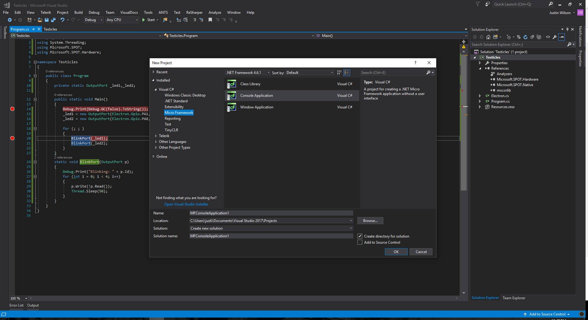
@Justin - Any tricks to get .NETMF running in VS2017? I haven’t tried…
How you did using .NET MICRO 4.4 at VS2017 ???
Can you provide a way - please how you did it.
I thought this is yours… Exen Mini - Smallest 32bit Arduino Comp Dev Board | Indiegogo
1 Like
@valon_hoti_gmail_com - I’m thinking that you just have to edit the VSIX to allow it to be installed in VS2017, but I am waiting for @Justin for confirmation.
@munderhill @valon_hoti_gmail_com
VS2017 NETMF VSIX
1 Like
Not me as i dont play well with Arduino 
1 Like
How did I not know there was NETMF 4.4?? Been using 4.3 this entire time
it’s been released but is not supported on any commercial scale hardware platform, certainly not GHI. There were some bug fixes and no new capabilities, so GHI have not put any effort into it - you can see TinyCLR is their focus. You don’t need to worry about 4.4.
Right on…I am definitely going to have to get me of Justin’s chips to play with Tiny CLR on at home…this is the only embedded project I will be getting paid to do but I definitely want to keep developing my skills / its a shit load of fun.
1 Like