No this is just technical datasheet no values ???
I don’t know what you mean, it is the STM32F401 datasheet:
It shows PB6 and PB7 are pins 58 and 59 here too:
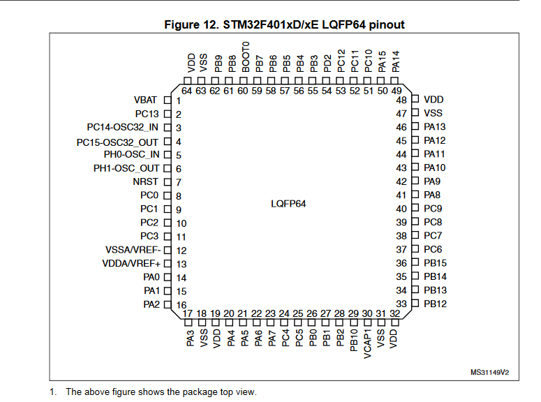
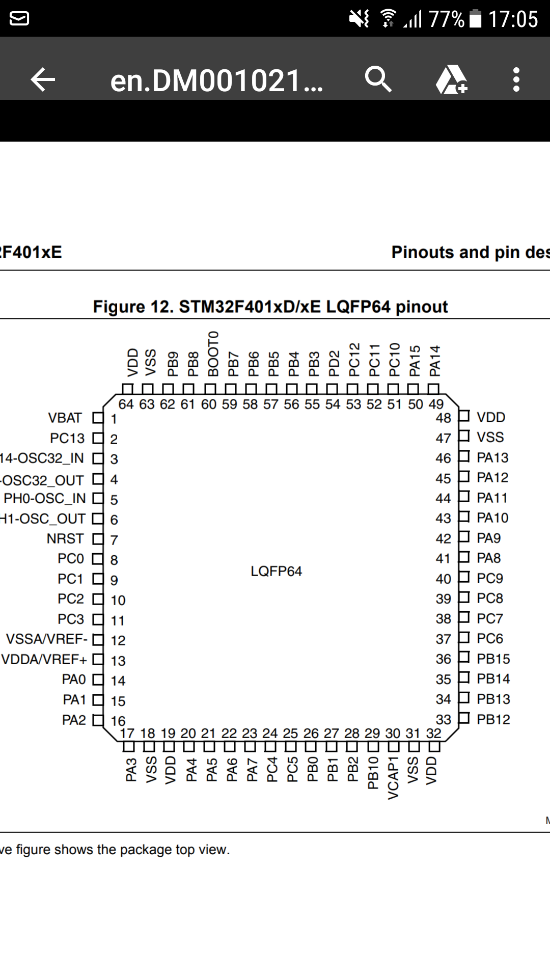
Yes shouldn’t that match what is in the code? How else will it know the I2C is supposed to be on pins 58 and 59?
You say it
PB6 and PB7
P Letter Number
P A 7
A=0
B=16
C=32
D=48
E=64
So formula to calculate pin values for pins PB6 is 16+6=22 and for PB7 is 16+7=23
so in this way you need to declare pins in devic…
I understand how that formula works that you gave but I do not understand why it is done like that and why it doesn’t match the data sheet/
Sheet is technical (hardware) purpose
Solution folder
device.h … is just solution template to tell what should be done compiler to create firmware (and to make interpreter which will act based on your defination)
Declaration on software will know exact which pin is
You are confusing logical pin view of the core and physical layout PIN number. The code need to use port PIN number as @valon_hoti_gmail_com is explaining you
Here is a post where someone was confused about the same concept:
I still don’t understand
1 Like
The datasheet tells you that physical pin 58 is port B bit 6. This is needed for schematic drawing not for software pin programming
1 Like
So saying physical pin 58 is port B bit 6 is not the same as labeling it PB6 in the software pin programming? They are totally different?
Yes, Netmf has pin numbering as @valon_hoti_gmail_com has explained. Forget about physical pin number. It is different for other MCU package and it is not needed for netmf pin reference.
Software based pin values PB6 (22)
trigger physical pin59 on mcu
I just need to make sure that the netmf pin numbering matches to the physical “triggering,” shown in the datasheets.
Yes that is what I have been struggling to understand. How do I even know if I am mapping it right though? If MOSI1 is physical pin 57, how would I know what to make that in the software?
Software based pins you just use formula that i told you and hardware will know exact what pin is
And sheet you need to use only for hardware purpose
So in that case, wouldn’t the netmf software mapping be the same for everything? I still feel like I am not fully understanding some aspect of this. Like how one decides in the software which pins are SCK, MISO, MOSI, etc if it has nothing to do with the hardware.

Here I understand that PA5 = software pin 5 BUT how does one know that is an SCLK pin (and which one)?
1 Like
You decide which ones you want to use as scl or sda for i2c
For example :
You are used pb6/pb7
i used pb8/pb9
And same way you may apply for spi (did you want just one or two or three spi pins…)
I just want two sets of SPI pins (SPI1 and SPI2). Won’t PB6/PB7 translate to different physical pins than PB8/PB9 though?
oh wait I think I am starting to understand it now. Jeez this is an odd way to go about things.
@valon_hoti_gmail_com Ok this I think I fixed it:
#ifndef PLATFORM_STM32F411NUCLEO_SELECTOR_H
#define PLATFORM_STM32F411NUCLEO_SELECTOR_H
/////////////////////////////////////////////////////////
//
// processor and features
//
#if defined(PLATFORM_ARM_STM32F411NUCLEO)
#define HAL_SYSTEM_NAME “STM32F411NUCLEO”
#define PLATFORM_ARM_STM32F4 // STM32F4XX
#define STM32F40_41xxx
#define USB_ALLOW_CONFIGURATION_OVERRIDE 1
//
// processor and features
//
/////////////////////////////////////////////////////////
/////////////////////////////////////////////////////////
//
// constants
//
// System clock
#define SYSTEM_CLOCK_HZ 84000000 // 84 MHz
#define SYSTEM_CYCLE_CLOCK_HZ 84000000 // 84 MHz
#define SYSTEM_APB1_CLOCK_HZ 42000000 // 42 MHz
#define SYSTEM_APB2_CLOCK_HZ 84000000 // 84 MHz
#define SYSTEM_CRYSTAL_CLOCK_HZ 12000000 // 12 MHz external clock
#define CLOCK_COMMON_FACTOR 1000000 // GCD(SYSTEM_CLOCK_HZ, 1M)
#define SLOW_CLOCKS_PER_SECOND 1000000 // 1 MHz
#define SLOW_CLOCKS_TEN_MHZ_GCD 1000000 // GCD(SLOW_CLOCKS_PER_SECOND, 10M)
#define SLOW_CLOCKS_MILLISECOND_GCD 1000 // GCD(SLOW_CLOCKS_PER_SECOND, 1k)
#define SUPPLY_VOLTAGE_MV 3300 // 3.3V supply
// Memory
#define FLASH_MEMORY_Base 0x08000000
#define FLASH_MEMORY_Size 0x00080000 // 512K
#define SRAM1_MEMORY_Base 0x20000000
#define SRAM1_MEMORY_Size 0x00018000 // 96K
//total GPIO PORTS A,B,C,D
#define TOTAL_GPIO_PORT 3
#define TOTAL_GPIO_PINS (TOTAL_GPIO_PORT*16)
//total UART TLL ports
#define TOTAL_USART_PORT 3
#define USART_DEFAULT_PORT COM1
#define USART_DEFAULT_BAUDRATE 115200
//used generic but SWO is PB3 it should defined otherway … on nucleo stm32f411ret6
#define TOTAL_GENERIC_PORTS 1 // 1 generic port extensions (ITM channel 0 )
#define ITM_GENERIC_PORTNUM 0 // ITM0 is index 0 in generic port interface table
//debug to be used …
#define DEBUG_TEXT_PORT ITM0
#define STDIO ITM0
#define DEBUGGER_PORT USB1
#define MESSAGING_PORT USB1
//total controllers
#define TOTAL_USB_CONTROLLER 1 // FS only
#define USB_MAX_QUEUES 4 // 3 endpoints (EP0 + 2)
//scok port
#define TOTAL_SOCK_PORT 0
// System Timer Configuration
#define STM32F4_32B_TIMER 5
#define STM32F4_16B_TIMER 1
// Pin Configuration
#define STM32F4_ADC 1
#define STM32F4_AD_CHANNELS {32,33,34,35,0,1,2,3,5,6,7,36,37,16,17} // PC0, PC1, PC2, PC3, PA0, PA1, PA2, PA3, PA4, PA5, PA6, PA7, PC4, PC5, PB0, PB1
//pwm
#define STM32F4_PWM_TIMER {2,2,2,3,1,1, 1, 1, 2, 2, 3, 3, 4, 4, 4, 4, 2, 3, 3, 3, 3} //Not sure what these should be
#define STM32F4_PWM_CHNL {1,2,1,1,1,2, 3, 4, 1, 2, 1, 2, 1, 2, 3, 4, 3, 1, 2, 3, 4} //Not sure what these should be
#define STM32F4_PWM_PINS {0,1,2,3,38,39,40,41,8,9,10,22,23,24,25}
//spi
#define STM32F4_SPI_SCLK_PINS {19, 29} // PB3, PB13
#define STM32F4_SPI_MISO_PINS {20, 30} // PB4, PB14
#define STM32F4_SPI_MOSI_PINS {21, 31} // PB5, PB15
//i2c
#define STM32F4_I2C_PORT 1
#define STM32F4_I2C_SCL_PIN 22 // PB6
#define STM32F4_I2C_SDA_PIN 23 // PB7
//uart
#define STM32F4_UART_RXD_PINS {10, 3} // PA10, PA3
#define STM32F4_UART_TXD_PINS { 9, 2} // PA9, PA2
#define STM32F4_UART_CTS_PINS {GPIO_PIN_NONE, 0 } // PA0
#define STM32F4_UART_RTS_PINS {GPIO_PIN_NONE, 1 } // PA1
// TinyBooter entry using GPIO
#define TINYBOOTER_ENTRY_GPIO_PIN 45 // User button
#define TINYBOOTER_ENTRY_GPIO_STATE FALSE // Active low
#define TINYBOOTER_ENTRY_GPIO_RESISTOR RESISTOR_DISABLED
//
// constants
/////////////////////////////////////////////////////////
#include <processor_selector.h>
#endif // PLATFORM_ARM_STM32F411NUCLEO
#endif // PLATFORM_STM32F411NUCLEO_SELECTOR_H