I have received a Fez Duino, and upgraded the firmware, created a new TinyCLR project in VS Community 2019, added the four NuGet packages, and successfully ran program to blink the blue user LED.
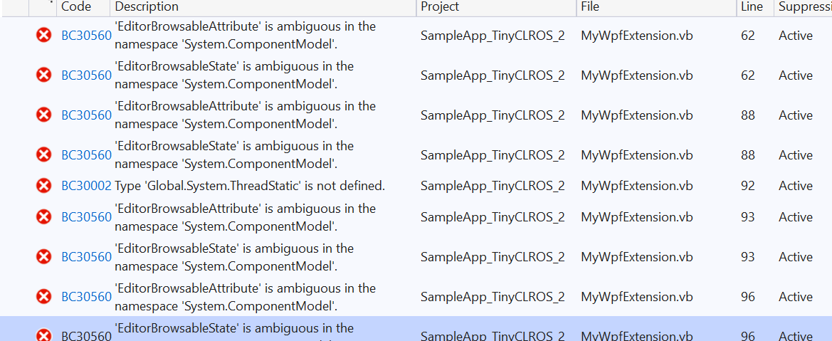
But, now, I need to do the same thing in a WPF project written in VB. I’ve created a new WPF project, in VB, and added the four NuGet packages, but the following line…
Dim LED = GpioController.GetDefault().OpenPin(SC20100.GpioPin.PE11)
…produces the following error: “‘GpioController’ is not declared.” And there are a few additional errors which look like this:
You need to physically set the mod pin, not in code. And you need a serial connection to your board. The dev board works easier if you are not sure how to wire a serial port properly
Really? I had the Panda 2 and it worked great out of the box - I wasn’t aware of any MOD pin. I used a library called, Serializer.NET, with it (from Trossen Robotics, I think) and it worked great right from my .NET VB software GUI interface. Just include the .dll’s, set up the imports (see sample code below), and that was it (no soldering, no pulldowns/pullups, no burning/flashing, etc.). I was hoping to have the same experience (or better) with the Fez Duino, but it doesn’t appear to be that straightforward.
Imports RoboticsConnection.Serializer
Imports RoboticsConnection.Serializer.Components
Imports RoboticsConnection.Serializer.Controllers
Imports RoboticsConnection.Serializer.Ids
Imports RoboticsConnection.Serializer.Sensors
Imports System.IO.Ports
Imports System.Threading
Imports System.Reflection
Imports System.Net.Sockets
Imports System.Text

Public BOT_SERIALIZER As Serializer
Public SERVO_8, SERVO_9 As ServoMotorController
Public LED_1, LED_2 As LedId
Public BOT_BATTERY_VOLTAGE As AnalogSensor
Public WHEELENCODER_1, WHEELENCODER_2 As WheelEncoder

BOT_SERIALIZER = New Serializer
BOT_SERIALIZER.PortName = TextBox_Serializer_Port.Text
BOT_SERIALIZER.BaudRate = 19200
BOT_SERIALIZER.Reset()
SERVO_8 = New ServoMotorController(BOT_SERIALIZER)
SERVO_9 = New ServoMotorController(BOT_SERIALIZER)
SERVO_8.ServoMotorId = ServoMotorId.ServoMotor1
SERVO_9.ServoMotorId = ServoMotorId.ServoMotor2

BOT_SERIALIZER.PumpEvents()
SERVO_8.Position = Math.Round(VELOCITY_CUR_L, 0)
SERVO_9.Position = Math.Round(VELOCITY_CUR_R, 0)
I think you are confusing things or we did not understand what you need.
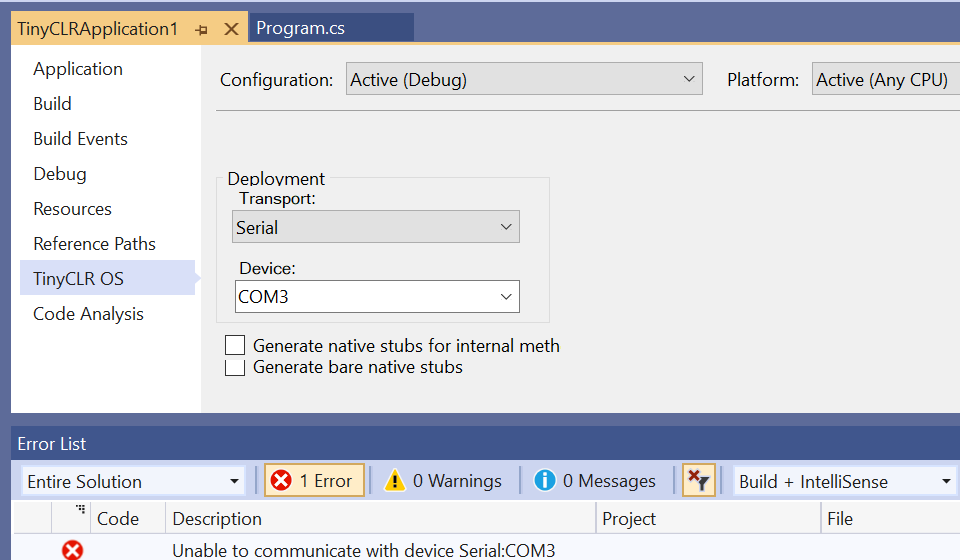
On panda with netmf and also on new boards with TinyCLR, you can’t debug and use USB at the same time. If you want to use USB in your code, you need to switch debugging to serial, which is done by connecting the proper serial port to your PC and pulling the MOD pin to the proper state, as explained in docs.
Okay - I’d like to try to do those two steps, but I need a clear, step-by-step tutorial, if someone can point me in the right direction how to do it for this board specifically (I found many random articles on the internet on how to create the circuit in various ways). I’m not good at soldering, but I can do the pulldown if it can be done on a breadboard - just need easy instructions how to do it. Also, how to set up the serial port.
Wayne, with his Panda, has a PC-based GUI app.
The Panda runs a netmf app, possibly is not written in VB, that controls the outputs for a robot.
The PC-App is sending commands to the Panda over USB, not while debugging of the netmf app is active, hence why no MODE pin change needed.
Wayne, the app you loaded onto the Panda is the secret sauce here. It is what you would need to replace if you want to do exactly the same thing as you have today. It seems likely that this app is not your code, but someone else’s, is that true? If that is someone elses’ code, do you have the code or the rights to it, so that you could investigate porting it to TinyCLR ?
The MOD pin on the Fez Duino is PD7. it is on the end of the board, right next to a GND pin and the 3v3 pin. It’s as simple as connecting that to either of those, as directed. And then you need a USB-Serial dongle (many cheap ones on ebay but YMMV on quality and support) and then just need to make appropriate jumper connections to pins on your board for whatever UART you select.
wire the PD7 to the GND pin (or 3v3 pin) - got it.
I’m lost on this second step - USB-Serial dongle from where to where? My laptop doesn’t have a 9-pin serial input and the card doesn’t have a serial input, either. Can you suggest what to wire for the jumper connections more specifically, please? Or, are you saying that I need to wire pins on the dongle to pins on the board? Sorry for the confusion, this step is completely new to me.
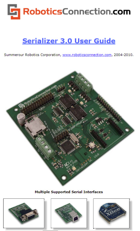
Also, I think that I can clear up the confusion. I had a different microcontroller card (Serializer.NET from Trossen Robotics) and I have a VB.NET program (created with VS) that was used to control the outputs on the microcontroller card which is mounted on a mobile robot (the commands are sent over WiFi (TCP/IP) or XBee or USB, when attached). The plan, a few years ago, was to upgrade to the Panda 2, but it never happened for whatever reason, so I didn’t know about the MOD pin. The Serializer.NET doesn’t require uploading/flashing anything, as they provide .dll’s to reference in the VB program for accessing the outputs on the card - it was crazy convenient. I found the documentation - here’s that card:
Okay, so I see USB-A plugs into the computer, and the six-wire end is wired to the board. For easiest/common connection, which pins do you wire to which color?
Page numbered 10, page 11 of the PDF, section 4.1 shows colours to function mapping. Then you need to choose what UART you’re going to connect to on your Fez Duino.
Of course, now we understand more about what you have and what you’re going to try to achieve, the good news is that once you make the connection with the USB module, you really can just use this serial connection for your app-to-Fez communication as easily as you could use the other USB port, because they both behave just like a serial port… I’d always prefer to keep the GHI device in “standard” and debug over the regular USB port.