@Gus_Issa can you check the schematic? Looks to me like UART3 isn’t labelled correct as it’s got TX and RX duplicated on different pins? (PC10/11 and PD8/9)
RTS and CTS are optional. I’d use UART7 if you want RTS/CTS, otherwise I’d just use UART3 or any of the other UARTS that are available on headers. I’d also suggest that you make sure things work on UARTs because of UART Dyslexia, before making permanent connections… RX on one side goes to TX on the other… if i say it often enough I may one day get it 100% right (but I doubt it).
good point, you need to use UART1 on Fez Duino, so PA9/PA10 (and you don’t get RTS/CTS). But honestly, I’d stay with debug on USB and just use the separate USB-Serial module to connect to whatever UART you decided you wanted.
For @Wayne, the key to creating your own hardware here will be replacing the control structure - how your PC app generates a command and transmits that to your Fez, that then transforms that to robot commands.
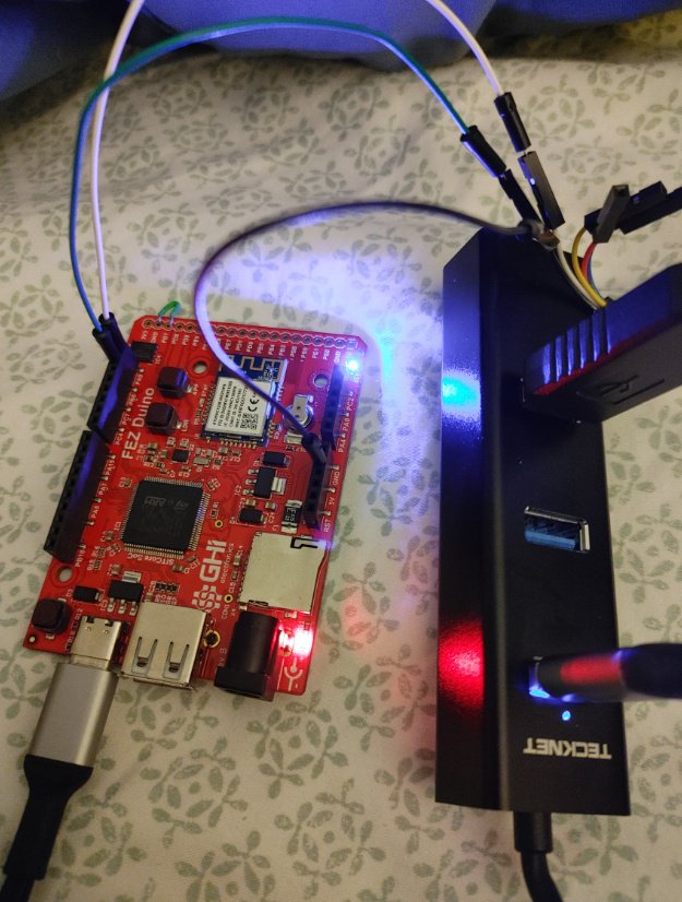
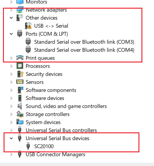
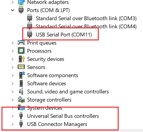
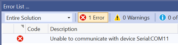
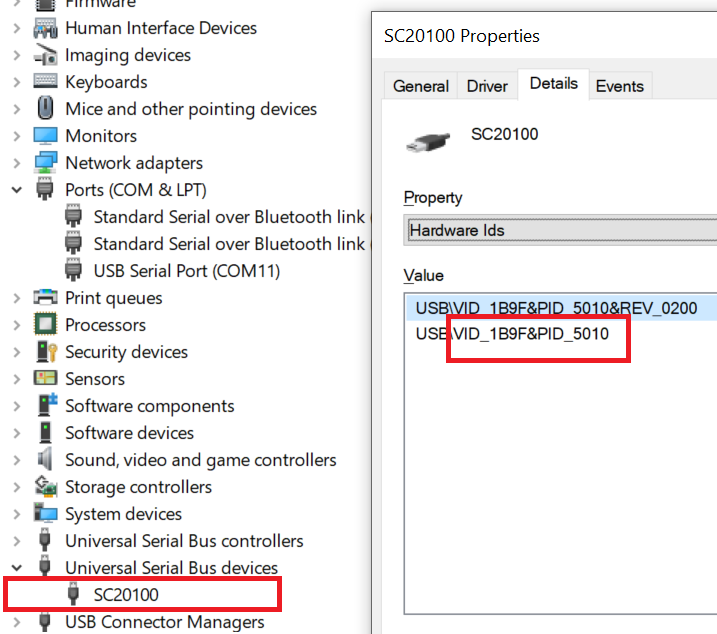
Okay, got the serial cable. Here are some images of the setup, and an image of my Device Manager (before and after installing the drivers for the new serial cable).
The setup (green wire is TXD, white wire is RXD, black wire is GND):
step 1 is to do nothing fancy in a test app. It needs to spit out “hello world” on the debug line. Do that with the regular USB connected and the MOD pin not pulled low, and it should spit out into the debug window in VS.
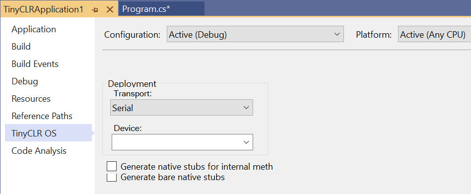
Step 2 is load the same app with the serial port connected and the MOD pin tied to GND, which should then spit the messages out the serial port and can be read with a serial port app (even something like putty should work) or VS should be able to see the device if correctly restarting debug over serial…
Got an interesting result from that. I did Step 1, changed VS to USB transport, and that worked. I did Step 2, with transport still on USB, and that worked. I did Step 2 again, with transport on Serial, and that failed (same COM11 error). So…now, I can deploy successfully, as long as transport is on USB (not sure why Serial doesn’t work), even without serial cable or MOD pulldown. Not sure what changed, or why serial cable doesn’t work, but it works good now just with the USB. Actually, I kind of prefer it this way without having to attach the serial cable.
i don’t understand your results, really. Nothing logical there.
MOD pulled low is a requirement - when you do that, debugging output is directed to the serial port. Without it, debugging output goes to the USB port.
Until you move to serial debug, you can’t use the onboard USB for anything other than power/debugging. So until you get the correct behaviour there, I think you’ve still got more testing and diagnostics to do.
But as I said, for me the best bet would be to use any COM port on the Fez as my serial in/out control mechanism in my app, and leave MOD pin alone. If you’re happy with that, go for it.
A question came up - where can I get the values for the UsbClientSetting? From looking at the values in the Properties on the Universial Serial Bus devices SC20100:
        var usbclient = UsbClientController.GetDefault();
        var usbClientSetting = new UsbClientSetting()
        {
            Mode = UsbClientMode.WinUsb,
            ManufactureName = "GHI Electronics, LLC",
            ProductName = "SC20100",
            SerialNumber = "12345678",
            Guid = "{88bae032-5a81-49f0-bc3d-a4ff138216d6}",
            ProductId = 0x5020,
            VendorId = 0x1B9F,
        };
        usbclient.SetActiveSetting(usbClientSetting);
        usbclient.Enable(); //this fails and must reset board
I’m going to use the usbclient to read incoming data, but I’m completely guessing at what to put here (except I pulled the ProductId and VendorID of the properties). The guesses are wrong because the program fails at the usbclient.Enable() command. Is there a better way to obtain those values?