Trying to set up the RTC I was recommended by @Justin
I have communication and can read/write to the registers, but I do not understand this register map.
Can someone please give me an example of how I would set the time to these registers as well as decode them? My I2C works I just need help with how the buffers should be set up.
@Justin can you explain to me how I would store the year 2017 in the register mapped below? I understand it a little better now that I see how you turn one digit into 4 bits but what about the registers that are only 3 bits like 10 seconds in 01h.
If I was storing just 17, would I store DecToBcd(1) in the 10 years bits and DecToBcd(7) in the year bits? But what about the 2000 part? I read something about bits for the centuries too would I use them for the 2000 part or would I just put 200 in the 10 years bits?
@Justin those values I read back are the date in integer form and don’t have to be converted from bytes (if I do it gives me insane numbers in the millions). So I think Mike is on the right track…it must be returning unsigned int8’s. Woudn’t I want to change the return type of BcdToDec in that case to keep it straight?
public byte Read(int Address)
    {
        var Data = new byte[1];
        var xActions = new I2CDevice.I2CTransaction[1];
        xActions[0] = I2CDevice.CreateWriteTransaction(new byte[] { (byte)(Address & 0xFF) });
        Thread.Sleep(5);
        if (I2C.Execute(xActions, 1000) == 0)
        {
            Debug.Print("Failed to perform I2C transaction");
        }
    }
Its the code I used for the EPPROM. I think the reading is working correctly, it would probably be better to have Read() take in a hexadecimal instead of an int so that I can directly follow the register map in the data sheet. What do you think?
@Justin I have quick question about pull ups on my I2C lines + multiple devices. So the G30 data sheet says it needs 2.2k pulls on SDA and SCL. My EEPROM just needs 2.2k on one of them, display needs them on both, and so does this RTC. So would I have a resistor on the G30 pin, then VCC, then another resistor on the other side of VCC to act as the pull up for the slaves? And what about the EEPROM only needing a pull up on one line, will having pull ups on both affect it?
hexadecimal is a REPRESENTATION of a number. INT is a size of number. 0x80050041 is a hex number, but it’s nothing to do with a size. Your Read() can be called like read(156) or Read(0x9C), and it’ll behave exactly the same. It’s really important to get the difference of these fundamental concepts…
What Justin really needed you to do is not to reproduce the raw read function, but show the way you repeatedly call it to get the time values. As you can see from his driver, it’s all about the sequence of calls to the different registers, showing us that would have showed how you needed to modify your code to make it work.
I thought int stood for integer which means whole number and is by default 16 bits. Then there is 8bit and 32bit as well correct? I think I am misunderstanding what you mean by it being a size of a number. I did not realize hexadecimal was interchangeable like that, thank you for clarifying.
I am calling read like this (note - I was not sure of a good way to automatically determine the size of i for this loop so let me know if you think of something):
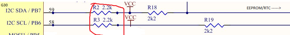
@Justin As for my pullup question, I understand that you only need one set of pullups for all the devices, but in the G30 datasheet it also says it needs pull ups. Doesn’t that mean the g30 needs a resistor between itself and VCC and the slave devices also need a resistor between Vcc? Here is what I mean (imagine slave devices are off the page to the right):
You need one set of pullups for the signal lines. It has nothing to do with what devices, or how many devices, are attached. The pullup does this - when nothing is actively driving the signal low, it is passively pulled high by that pullup; so a device that reads this (in your case it’s the G30) is just sampling the line and seeing it is high or low, and driving the signal when it’s sending. ONE SET.