How would one wire the RelayCape for a motor? I tried an automotive LED but was unsuccessful so far.
…
I used a 12v battery:
+ Negative terminal on the battery to LED negative.

    + LED negative to NO on the RelayCape.

+ Positive terminal on the battery to COM on the RelayCape.
…
I will be trying a motor soon. I will keep you updated on if I can make it work.
I noticed that the Relay2 on the Cape clicks when the source I run is running w/ a timer and pin control.
The LED also turns off and on when the timer starts and stops.
Seth
P.S. Please send any guidance on this issue. I think it may be that my automotive LED is not equipped w/ the proper circuitry. I am updating my image to an older image but the same kernel. I will update you once I make the same tests on this image.
Okay. Thank you. I will look elsewhere for wiring info. I guess since I cannot mux my pins, it may not be a wiring issue but I will study some more items online for wiring my switch.
“NO” means “Normally Open”. This means that the connection is NOT normally turned on.
“NC” is normally closed, ie the normal state is connected.
With a relay like this, all you want to do is have the negative of your LED-module connected to the -ve of the battery, and the positive of the LED-module connected to either COM or NO, doesn’t matter. The other connection from the relay (NO or COM) connects to the battery +ve.
Seth here. I think this automotive LED has, like Mr. Brett stated, a couple of other components in it outside of just the bright, off-road LEDs.
Seth
P.S. Sorry it took so long to reply. For everyone reading this idea, I just ordered some alligator clips for testing. I think I need to get some easily accessible equipment before further testing this product.
The fact your 12v LED “sparks” when you direct connect it to the battery has me worried - don’t take this the wrong way, but it seems to imply you haven’t understood what the LED module is meant to do or what the cables are? The spark usually signifies a large current draw, which implies that this is an almost-short-circuit load. Assuming that you are connecting this to a normal “automotive” style battery, where there’s no chance you can short-circuit two terminals together with a single wire, it means the LED module is not suitable for 12v connection. No matter how you connect this, it’s only going to cause you issues. Do you have a web link to the module you bought? That might help us identify if it’s reasonable to expect this behaviour (but I strongly don’t think it should)
If we go back to the fundamentals here, any 12v “device” should be able to be connected to a working 12v battery without issue. The relay is as Gus says, just a fancy switching mechanism, to make, and break, a connection in one of the wires. Before you go destroying your BBB or cape, I’d prove that the device you want to play with can be used direct on the battery without shorting out, and once that happens you can move it to the relay.
I don’t understand what your point about “hindsight” and better leveraging the internet. We’re here and happy to share knowledge where possible.
@Gus_Issa…yes sir. I understand the ideas relating to the switch inside of the Relays on this Cape. It basically shuts on and off w/ it on NC/NO when the contact is made or taken away.
That is the most current, up-to-date info. I can find on these LED bulbs.
…
I am getting a set of alligator clips one day in the mail and hopefully soon. I might move on from this LED bulb.
The LED bulb has a set of seven contacts on it. It seems when I apply the ohm test to the lower half of the LED or a diode test w/ a DMM, I get no reading back. But, when I test the upper contacts, I receive some feedback.
When you have time to review these ideas and the link, please do reply. I was just thinking of moving on instead of trying to figure out what is wrong on my end w/ these LED bulbs.
ok so how did you connect those to a power supply if you don’t have alligator clips?
Judging by the feedback on the Amazon page, there’s also plenty of negatives about these bulbs… like they are polarised but they aren’t marked. And with 7 contacts, no wonder you didn’t figure out what the right ones to use was! I’m sorry but the product page isn’t any use here either… SYLVANIA 3157 WHITE ZEVO LED Mini, 2 Pack seems to be the one you have. Can you take photos of the modules and post here, so we might assist?
If I was looking to use a 12v LED module for testing, I’d just opt for something like this. It’s very simple, as there’s just two wires, no chance of messing up what is connected to what.
Lets see the pics and tell us what you see when measuring with continuity, ohms, and diode settings on your DMM when you connect combinations of those terminals. Remember to reverse the connections in each test too in case it’s the opposite polarity
Seth here. Okay. I will get on it soon. One of my LEDs are still okay to work w/ as of now. I will take a photo and annotate it.
Seth
P.S. I might just purchase your $9.00, two-lead LED pack for testing instead but first the photo and annotations. Please stay patient. I have other projects now since the Maker Faire in my city has been cancelled due to the COVID-19 spread. Stay safe and I will get on it!
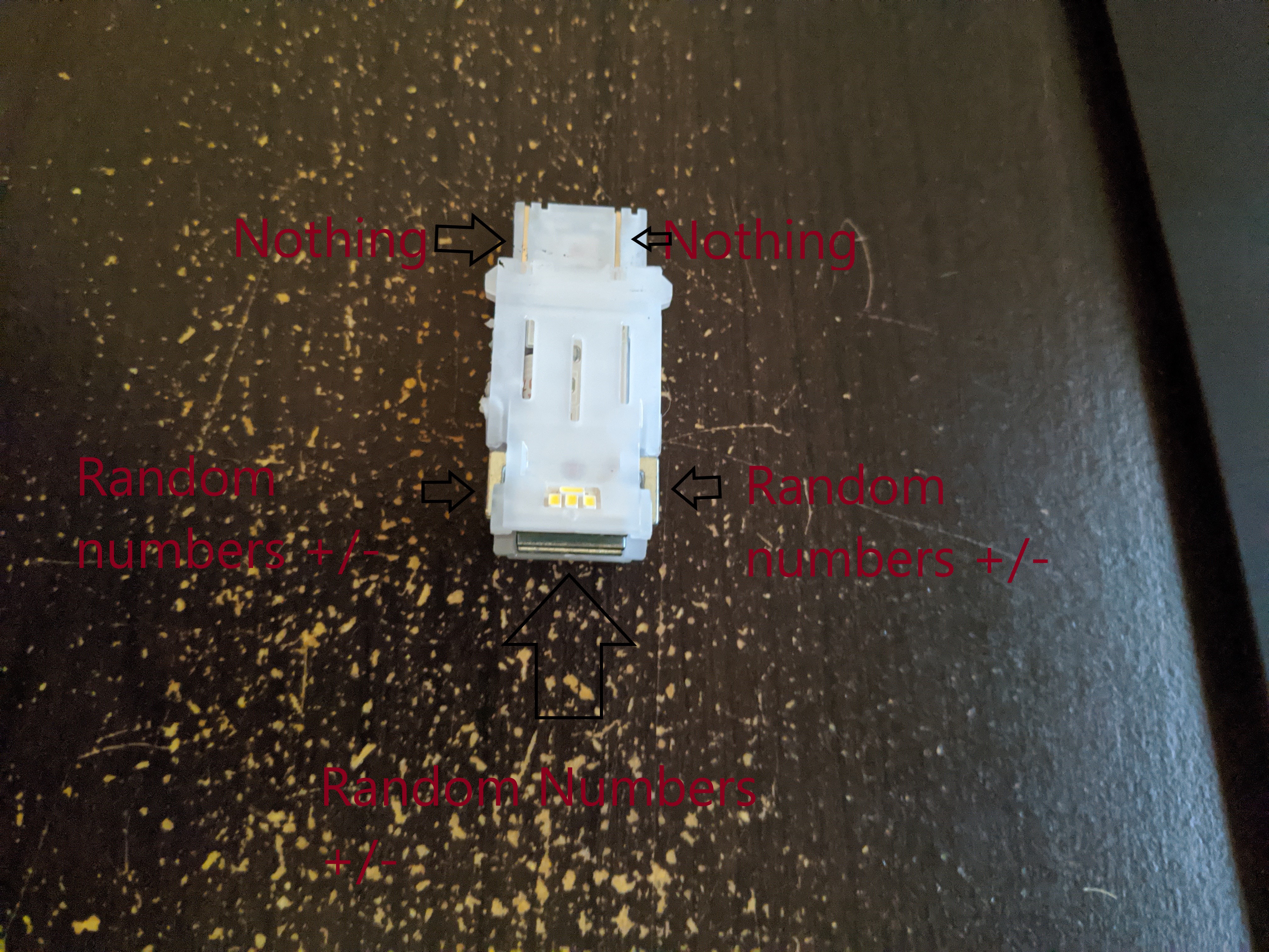
Here is a makeshift image of ideas. Where I typed random numbers, it was all sorts of random digits from 7.2 to 0.00 and back up and back down. The arrows show each of the contacts on this LED.
…
The +/- symbol is me checking w/ my DMM. I can put COM/GND on any section of the three contacts and test the other two contacts w/ the v, ohm, diode, and continuity test with the same result.
The result is a random number whether I put COM/GND on it and/or my testing/POSITIVE lead to another one.
The listed Nothing w/ the arrow is just that…
It read nothing back. I get no feedback and those are the leads I expected to get feedback from currently.
You need to be methodical here. Label all points as a letter, and then cycle through them. It seems there’s 5 connectors, so that’s A, B, C, D, and E. You then need to test AB, AC, AD, AE and document the results. “Random numbers” doesn’t mean much either - especially since one test I asked for was continuity, that’s either “yes, connected” or “no, not connected”, anything on the display is irrelevant, the buzzer (if your DMM is fitted with one) tells you the answer. Better pictures would also help, ie not just A PHOTO, so that we can actually see the connectors from different angles. A clean / single colour background would also help a lot.
But anyway, some of this is irrelevant too, with a DMM you can confirm the operation of the relay on the cape, all you need to do is to use continuity test mode and have your two probes connected to the COM and the NO contact, switch the relay in your code and you’ll see it should turn on and the DMM will buzz. But diagnosing the LED is also interesting
I will perform each test, make a solid background available for this LED, and try AB, AC, AD, and AE.
Seth
P.S. I know the Cape works. I am not discounting this idea. I already made the relay move and the LED turn on. I just am probably using the most intricate LED for automotive use I have come across. So, please bear w/ me while I test in the listed format, i.e. for continuity also.