Like described, I ordered some other LEDs that are for 12v applications. Funny thing, they are less expensive, already wired, and come in a 30 pack. Besides that idea, I have some better photos and a video to share.
The rest of the ohm tests are the same or a little off, i.e. about 0.01 to 0.02 off.
…
Now…the continuity test was odd. AB, AC, and etc were all showing continuity b/c I heard the beeping from my DMM. Also, the value of the continuity test kept changing value in feedback.
My diode test is the test I recorded in video to show exactly what this LED gives as feedback when applying the DMM to it. Note, The AB and BA was tested on video for reference.
If this helps you to understand that this is a very odd LED for multi-purpose use, I agree.
Seth
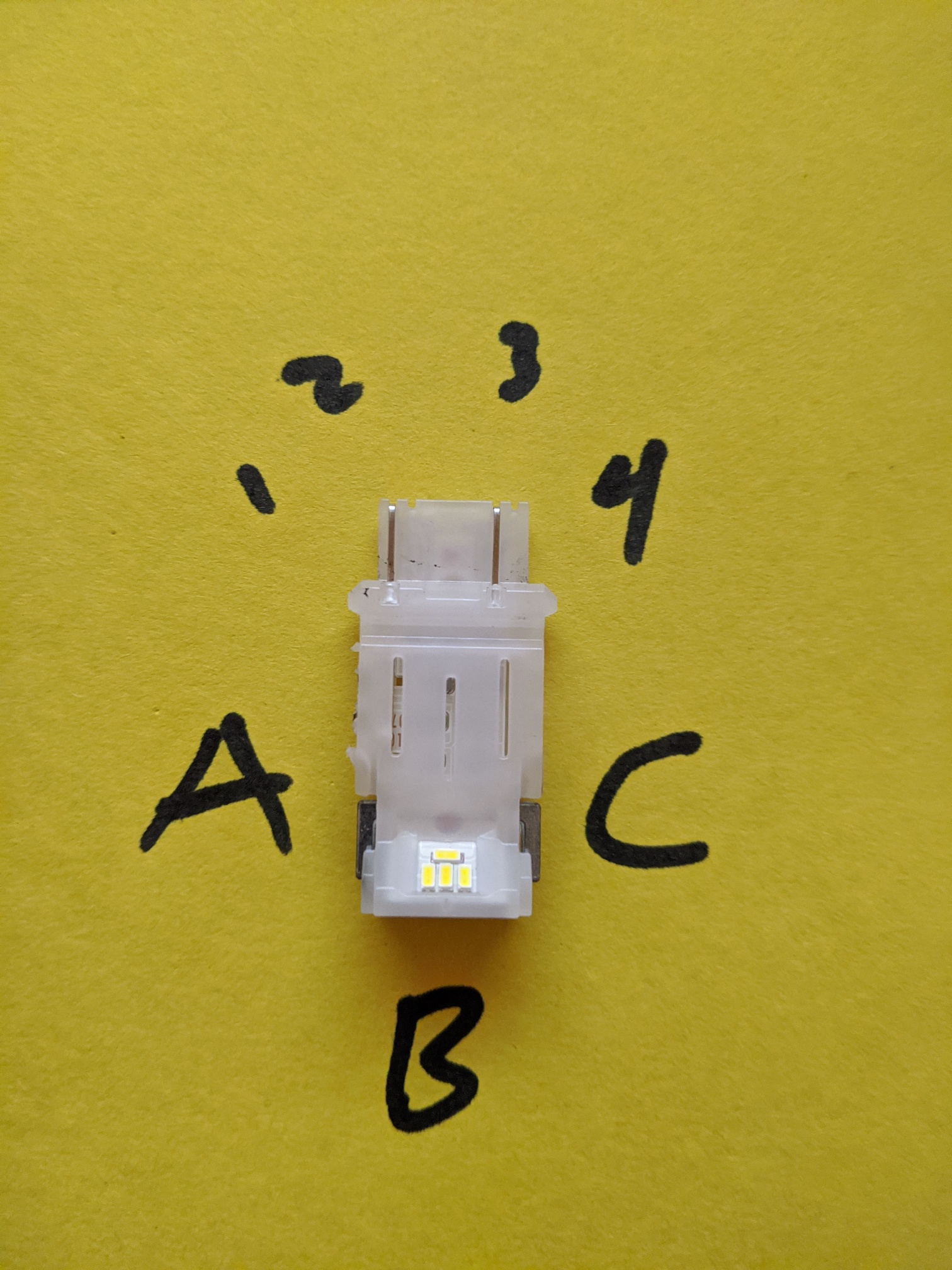
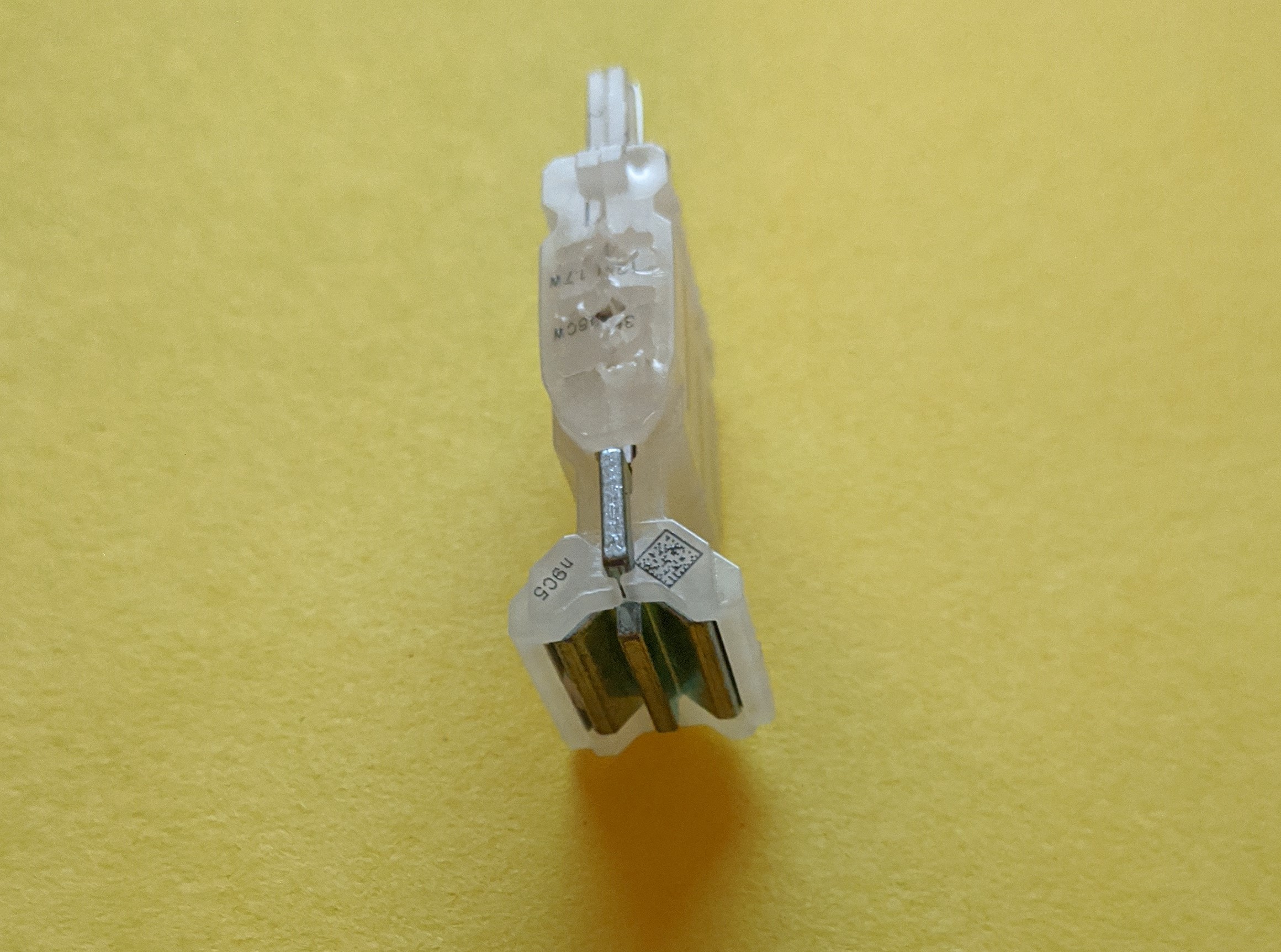
P.S. If you have any ideas, please do not hesitate to ask or give direction. Oh and the listed 1 - 4 numerical values on top provide no feedback at all. I forgot the side view photo. Here:
What about A1 A2 A3 A4 etc? And a pic of the number end?
In Australia, as far as I’m aware, we don’t have any connectors like this bulb would take, so I really am shooting in the dark. IMHO it’s most likely that the A/B/C side will be one polarity and 1/2/3/4 side the other. So the fact that AB and AC all show connected (as in the continuity test beeps) would show that too, so it’s critical to measure the 1/2/3/4 continuity to each other, then measure the heck out of everything between the two ends.
you realise that in some circumstances OL means something other than out of range? We’re trying to understand the specifics of this LED, which means you need to measure ALL aspects. A1 A2 etc and 12 13 14 etc, in all modes. I think what OL will mean is that there’s no continuity (meaning they’re not a dead short).
Most of this is actually being methodical about your testing and specifically reporting back your results. Just because something isn’t connected (beeping when using continuity mode) doesn’t mean that’s a bad result, that’s actually a good thing !
And now going back to your original “failure” when you connected things and you got a spark. What terminals were you connecting to ?
It is easy to work this out. They use a standard automotive socket. Your 2 contacts are on the 1234 end. The ABC in your image are the heat sink for the LED’s.
This is the socket they plug into.
You should find that 1 + 2 are shorted together and 3 + 4 too. The polarity can be checked with your meter on DIODE tester if the internal LED is exposed to the connections but it is unlikely as there will be some form of constant current control built into the LED module. I am assuming this as the will tend to be flickering without.
Unlike the incandescent lamps they replace, these are likely polarised unless that have a bridge rectifier on the input. They don’t appear to be marked but the comments on the Amazon website indicate they only work one way around.
Apply a small voltage, say 2V to pins 1 + 4 and see if the LED lights up. A current limiting power supply is the best way to test these.
@Brett: Sir, okay. 1 - 4 from my DMM receives nothing back, i.e. no feedback no matter what test I make.
@Mike: Okay, sir. I could. This was a thought at one point. I tried to dissect it but the plastics on the outside just warped instead of coming undone. I have a spudger now and I can try a little more on the dissection on one of my LEDs.
@Dave_McLaughlin: Hello sir. Yes sir…I found those also. I have a current limiting supply onsite. I will use this idea to see if the LED lights. I guess if necessary, I will make a purchase of the bulb socket.
Seth
P.S. Anyway, thank you all for the support thus far. I will keep at it.
hey @silver2row hope you’re doing ok. Was just reviewing your comments here.
If what @Dave_McLaughlin pointed out earlier is true with those terminals, then you are not getting readings from your DMM correctly.
If 1 and 2 are the same purpose, then with a continuity test they should show as connected - so testing “12” should beep at you. Same for 3 & 4, testing “34” should beep, and testing 13, 14, 23, 24 should not.
Yep, doing alright over here. I have not gotten the socket yet. B/c of COVID-19, things are kind of at a halt.
…
So, I will put the time waiting into learning something about what I already own, e.g. Servos, some boards, and some chips w/ datasheets.
Seth
P.S. Okay…SO! I tried the PSU w/ the LED. Something is wrong or I need more test leads for the attempt. I put my PSU on 6v after it was on 2v and nothing. Now, I am not sure if I need to apply the entire 12v for this LED bulb or not but I will test that out at a later time. @Dave_McLaughlin, I will attempt another form of testing w/ my leads soon.
Seth here. Say there are four sides b/c of the four contacts, e.g. not the Heatsinks (A, B, C). So, 1 - 4, I tested these values as:
I clipped GND from my PSU to a side on the LED which totaled two contacts.
1 and 2 = GND
I clipped Positive from the PSU to the adjacent side of the LED, i.e. the other two contacts left.
3 and 4 = Positive
and…
I clipped GND from the PSU to 3 and 4 on the LED.
I clipped Positive to 1 and 2 on the LED.
What I did not try was this idea:
GND on the PSU to 1 and 3 and/or 2 and 4.
I also did not try Positive on 1 and 3 and/or Positive on 2 and 4.
If your bench supply shows current, set the limit to something low to start with, maybe around 50mA or so. If the power supply doesn’t have any current display, use your multimeter in series to check the current.
You can use the full 12V if you limit the current to start with. If the bulb is not polarised, it will either work only one way around or it may have a bridge rectifier on the input allowing it to work in any direction. Applying power to both pins will determine this.
This is all pretty simple stuff and you should be able to get the LED working this way.
Yes sir…you are right. This subject of testing terminals is simple stuff. I will keep at it.
Seth
P.S. I will try the top two pins for GND and the bottom two pins for Positive next. The PSU has current on the dash. So, I can alternate current and then go to volts afterwards. 50mA? Why did you choose 50mA?
Well, this happened. While trying to test the LED bulb at the four terminals, two broke off. So, I have one left, i.e. one LED left.
Anyway…I should get the socket. Amazon is giving me issues right now. So, the socket will not arrive until the end of May (for some reason).
Seth
P.S. Anyway, thank you. Testing specific terminals at 25 to 50mA proved invaluable for now b/c there are specific pins that need to be examined. The way this bulb is set up prevents me from testing it w/out a socket.