Working on a design to use the UCM development board, would like to start on some of the mechanical mounting issues. Is there a drawing showing mounting holes dimensions, and placement of connectors? The top silkscreen artwork would be useful as well to verify connector(s) pin assignments.
The actual UCM development boards are still back ordered on Mouser till Sept. 17. so this would help in preparing for their arrival at our site.
Looking forward to using UCM modules for our instrument manufacturing test equipment. Our instrument has two custom G400 designs plus the option to for a G120 for power monitoring. Currently we are using the G400 Development boards, but we don’t need the display.
I have the breakout board but prefer the UCM development board for our use case. (I use a forty pin right angle Wire Wrap connector, so I only connect the pins I need, the breakout board when used with wire wrap makes it harder to go back and add extra pins if needed)
One other comment / suggestion would be to used keyed 40 pin connectors, on the development boards, helps with which way the wire wrap board faces and alignment with all forty pins.
Anyways the UCM looks very attractive for us in manufacturing and quick prototypes in development.
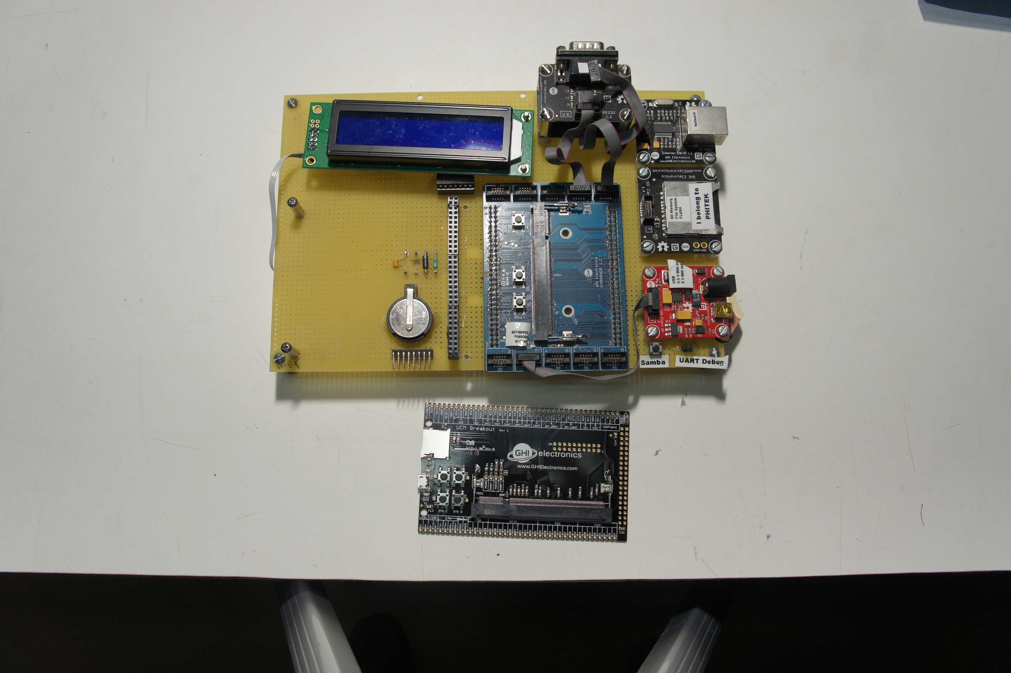
Here is a picture of an earlier breakout board, there is some advantages to the extra power connector, USB / Serial Debug ports, and possibly networking options in the future. This picture include the UCM breakout board as sold.
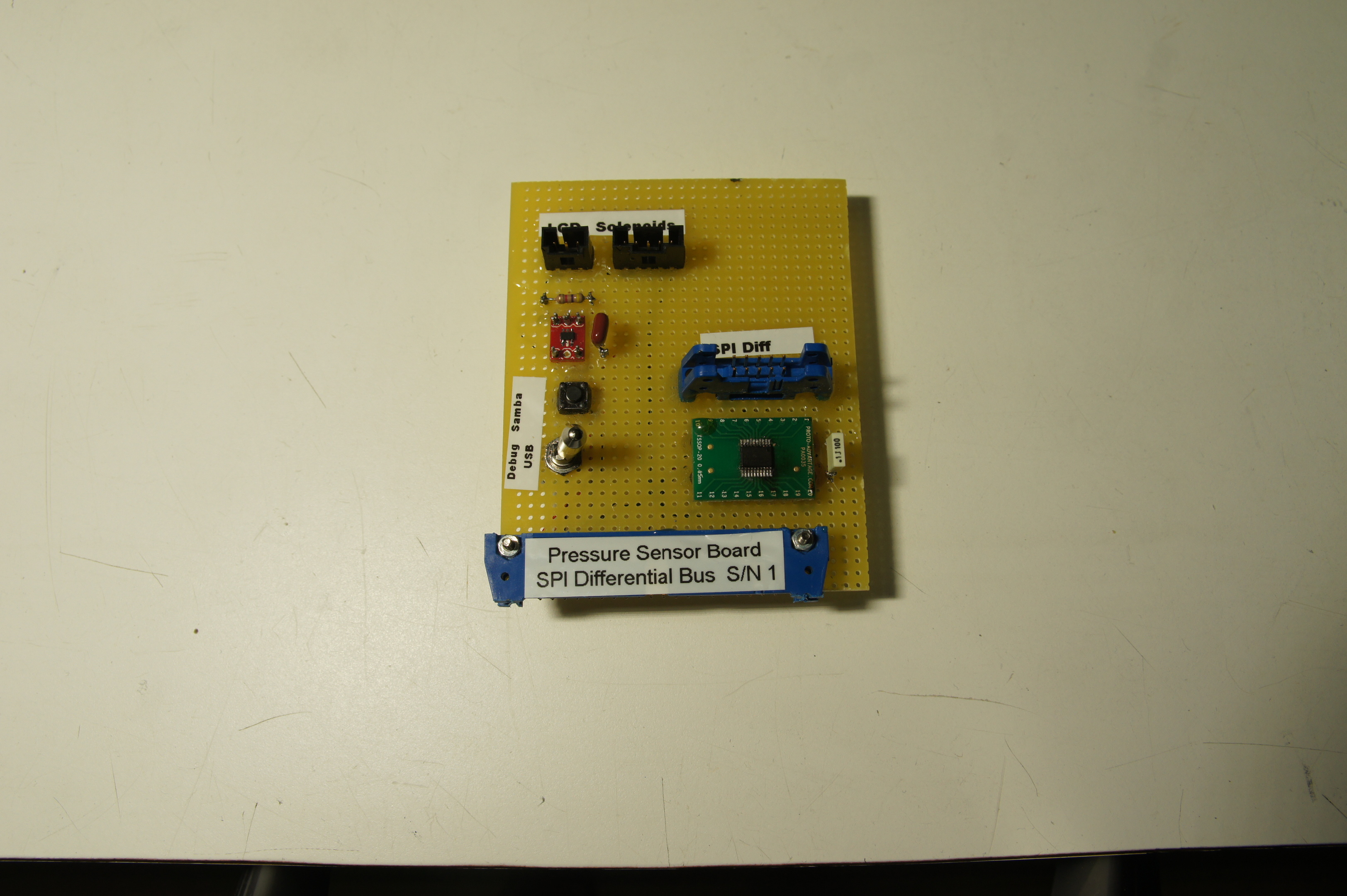
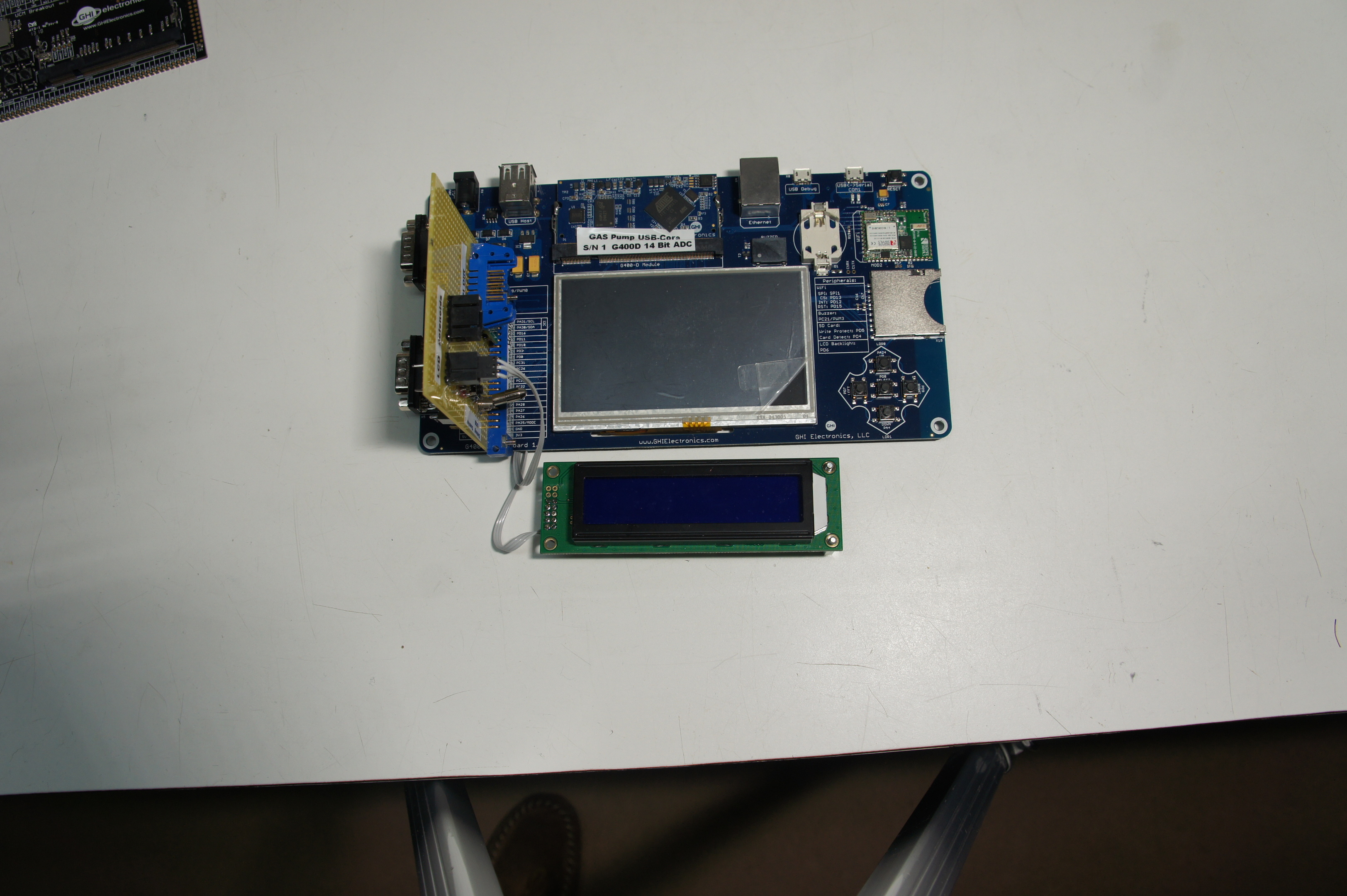
The G400 Development board is our current choice, with an adapter board on the 40 pin connector, notice the USB / Serial Debug mode switch, Samba push button, a small 3.3 to 5 V logic shifter for the single Tx signal that runs the 2 x 20 display (low resource count) and a SPI to differential transceiver that goes to our pump pressure sensor, barometric pressure, and solenoid valves for some custom bellows pumps. The smaller connector is power and Tx for the LCD display and four GPIOs for the solenoid valve.
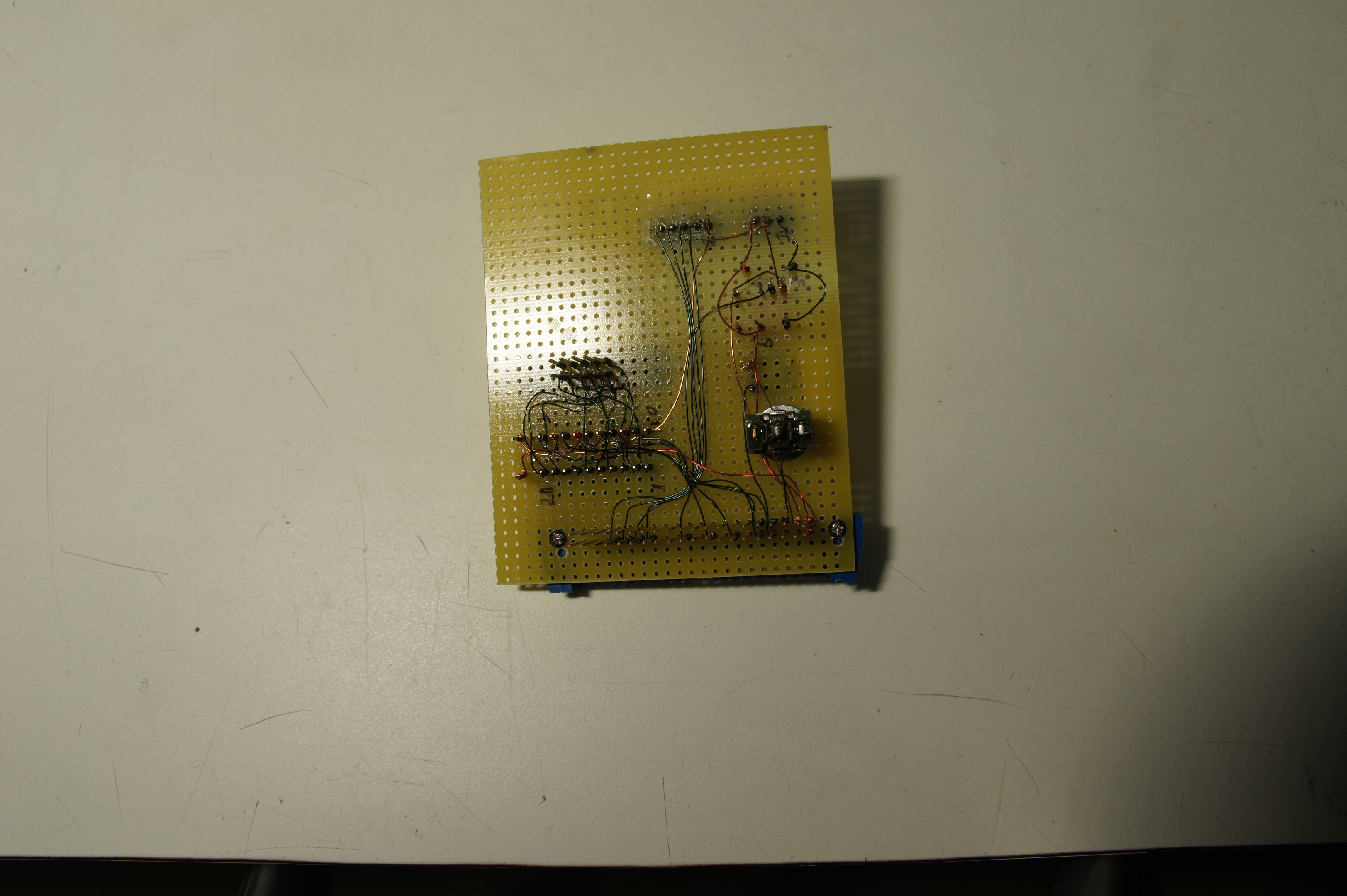
Also a picture each of the front and back side of the adapter board. The only downside is the larger height in the enclosure requires.
The UCM development boards are only for instrument production test stations, like our pumps, stepper motor controllers. There are two G400 custom designs in the instrument. Just to be clear. The one G400 design uses an FPGA for electrical pulse timing and sampling, which have real time requirements.