On the SC20100 I’m having issues with GPIO input on PE0 / pin 97. I have the same circuit on other pins and those work correctly. There are two issues that lead me to believe this may not be wired up correctly internally:
-
The internal pull-up resistor is not working. I have an external pull-up resistor space on the PCB and was testing with it removed to reduce component cost/complexity. Internal pull-ups work correctly on other GPIO input pins I tested.
-
It always reads logic level 1 (high) regardless of whether the pin is high or low. I have tested this by disconnecting it from the rest of the PCB and using external pull-up and pull-down.
  Gpio = GpioController.GetDefault();
  MainPowerSwitchPin = Gpio.OpenPin(SC20100.GpioPin.PE0);  // PE0 = const 64, actual pin #97, both delta 14 from PD2 values
  MainPowerSwitchPin.SetDriveMode(GpioPinDriveMode.InputPullUp);  <-- Always reads 1, pull-up doesn't work

  BattPowerSwitchPin = Gpio.OpenPin(SC20100.GpioPin.PD2);  // PD2 = const 50, actual pin #83
  BattPowerSwitchPin.SetDriveMode(GpioPinDriveMode.InputPullUp);  <-- Reads 0 and 1 correctly, pull-up works
Can someone double-check all the definitions for this pin are correct internally?
What board are you testing on?
We have tried on SC20100Dev and look work fine. Logic is 0 if connect to GND, 1 if VCC.
1 Like
Production board migrated from G80 - all the circuitry has been vetted as it worked with the G80. I have another issue on the adjacent pin too, PWM on PB9 isn’t working. PWM on adjacent pin, PB8 works just great. Normal 25khz PWM on that pin, but PB9 is dead - no high or low voltage.
        EvapFanPWMPin = PwmController.FromName(SC20100.PwmChannel.Controller16.Id).OpenChannel(SC20100.PwmChannel.Controller16.PB8);
        EvapFanPWMPin.Controller.SetDesiredFrequency(25000);
        EvapFanPWMPin.Start();

        ExhaustFanPWMPin = PwmController.FromName(SC20100.PwmChannel.Controller17.Id).OpenChannel(SC20100.PwmChannel.Controller17.PB9);
        ExhaustFanPWMPin.Controller.SetDesiredFrequency(25000);
        ExhaustFanPWMPin.Start();

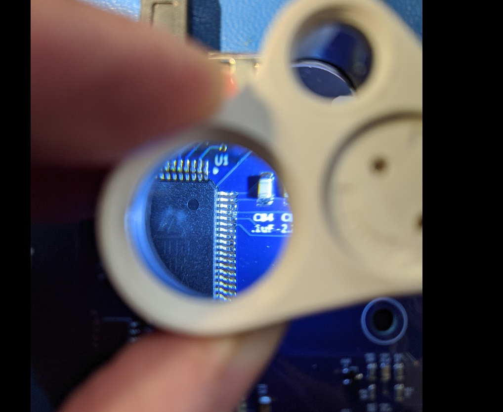
Argh. MUST get these produced at fab house. Tiny little solder bridge.
2 Likes
Even after removing the bridge both pins exhibit the same behavior. I’m don’t see how that solder bridge could have damaged them as the GPIO input is high impedence input and nothing feeding them has any power… PWM output connected to high impedence GPIO input would not have damaged the pins I would think… Of course it seems like too much of a coincidence at this point and I’m assuming it did somehow damage them.
I never ever build one prototype board, and what you are seeing is exactly why.
Why? Are you “chicken”
(think Back to the Future)
2 Likes
Interesting idea, building more than one. However these can several hours to hand build and the BOM is not cheap. I haven’t had this problem before and usually building one of an iteration is enough to sort out the “whoops” mistakes…such as moving my DAC circuit to a non-DAC pin when optimizing trace routing… 
How much time did you spend on troubleshooting this versus building another one that’s what I’m talking about