Either I’ve really screwed up my circuit design, I have dozens of bad 32,768 crystals, or I’m not understanding something with regards to getting the real time clock to work on the G30.
I’ve assembled 4 prototype boards now and I keep expecting to see a resonating oscillator on those lines, on the scope, but so far, absolutely nothing. Lines are just held low. VBAT has a 3.3v cell and 3.3v rail driving it through a schotky, I’ve got the crystal’s supplementary capacitors figured out (it’s 7pf and I arrived at 10 for my caps; (7-2)* 2 = 10 for c1 /c2.)
But that oscilator is not working, at all.
Is there something I have to do in code to get it to start working?
Or do I have to go back to the drawing board and figure out what I did wrong on my design?
I’m assuming there has to be something I missed. PC14 / PC15 are usable as GPIO ports, right? And that’s probably what they are sitting there doing right now, acting as inputs, while the crystal circuit on them is sitting dormant with no supply voltage.
So how to change them to enable RTC?
I don’t now if this will help but I am designing a board with a 25MHz crystal. I have ordered the STM32F4DISCOVERY board I will need to replace the crystal to test my Ethernet connections. I just watched this video it might help???
Ok nevermind, the stupid thing was working. I kept looking for it with my scope but didn’t have the scope set up right.
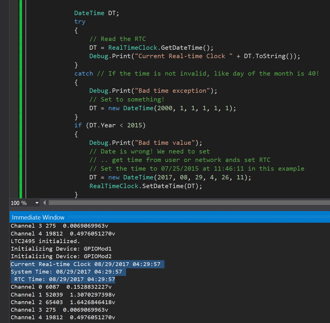
This is after pulling the power and letting battery drive it, plugged back in, re-ran program, and it shows RTC was still being tracked
Dropped the example code in and this is what I got
So we’re good.
Next time I try this I need to remember to crank up the sensitivity of my scope. I had to have it on a 10x probe at 10mV with 10us timing to see the resonator
1 Like