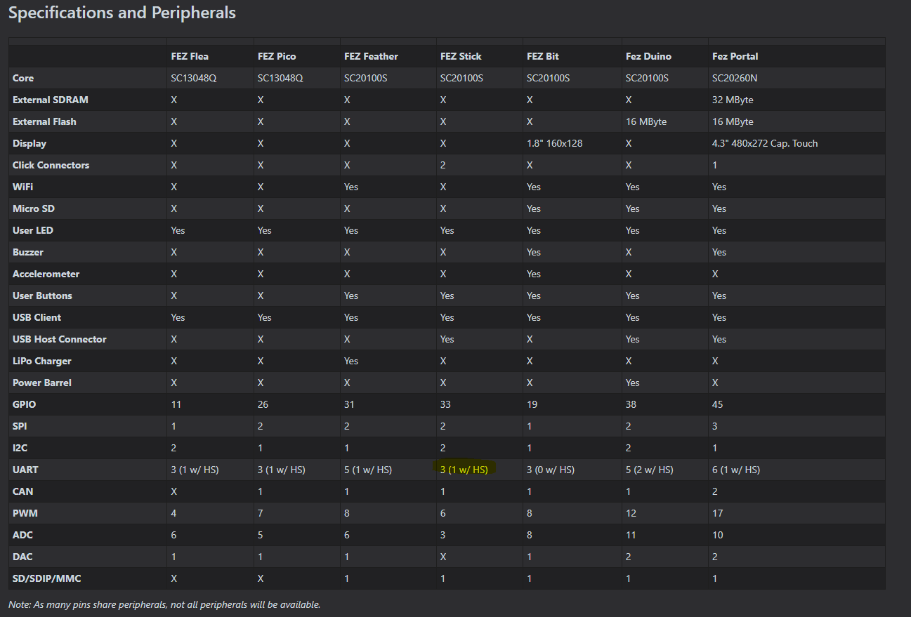
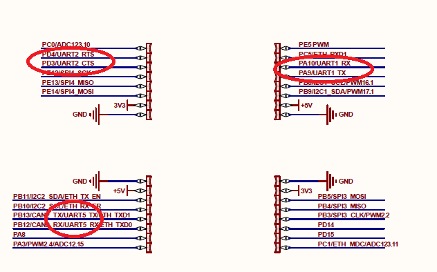
Hi on the site it says the Fez stick has 3 uarts, but its not clear where the thrid is exposed. Based on the schamtic and module I can see UART5 & UART1 but thats it, cant see the third.
I get the note below saying about pin sharing and i can see uart 5 pins are shared with can & eth, but if only two are physically avalibale on the board i think the documentation needs to reflect that. Unless it is shared with other pins and i cant see it in the schematic or on the silk.
Hi thanks for the response, excuse me for my naivety, but i can see the flow control lines also for uart 5, and yes for uart 2, but i don’t see the rx/tx for uart 2?
Thanks for the response, I needed to double check to make sure I was reading it all correctly. 2 is what I need but I also need to make use of the CAN bus so it means UART5 is unsuable for me.
Yes seems I will have to implement via the use of GPIO’s.
This example will move MOSI2 pin from PB2 to PC7, assuming AF6
// start by creating SPI2 to initialize the feature on PB2
// now transfer...
var settings = new Settings {
mode = PortMode.AlternateFunction,
speed = OutputSpeed.VeryHigh,
driveDirection = PullDirection.None,
alternate = AlternateFunction.AF6,
type = OutputType.PushPull
};
LowLevelController.TransferFeature(SC20100.GpioPin.PB2, SC20100.GpioPin.PC7, settings);
That is it, we will correct other statements in this section.
Thats cool, just looking for clarity on the assumption of AF6, what is AF6 and if i transfer tx & tx of uart2 on the fez stick to two other pins that are avalible on the board does the example still apply. Sorry for any inconveniance.
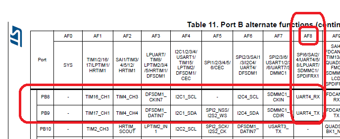
Firstly, you need initialize, SetActiveSettings() UART7 as usual, then
var settings = new Settings {
mode = PortMode.AlternateFunction,
speed = OutputSpeed.VeryHigh,
driveDirection = PullDirection.None,
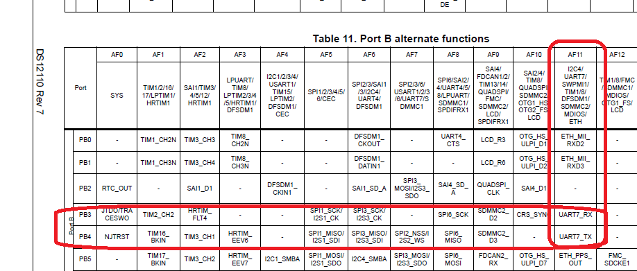
alternate = AlternateFunction.AF11,
type = OutputType.PushPull
};
// Transfer PE8 tx to PB4 tx, AF11 for UART7
LowLevelController.TransferFeature(SC20100.GpioPin.PE8, SC20100.GpioPin.PB4, settings );
// Transfer PE7 rx to PB4 rx, AF11 for UART7
LowLevelController.TransferFeature(SC20100.GpioPin.PE7, SC20100.GpioPin.PB3, settings );
You can transfer before or after called “Enable()”, but it has to be after SetActiveSeting(). This ‘SetActiveSeting()’ function will initialize original pins again.
If transfer after Enable() you may lost data because the port still use old pin till new pin updated, depends on how you setup your system.
Recommended is middle of SetActiveSeting() and Enable()
This information would be incredibly useful to add to the docs. A while ago I tried to get one of the can interfaces on a different set of pins so it wouldn’t collide with the ethernet PHY pins but couldn’t figure it out.
why this super power fully info is missing on doc
please provide more info on doc and an full example of it
(an marks all modules/board what have ability of AF)