I managed to get them powered and communicating (this is the L6480 chip). As soon as I give it a move command it reports that there is a over current condition. It’s method of detecting over current is by measuring the voltage drop between the Motor Supply Voltage and the Output. If its more than 1V (I’ve configured it for 1 volt) then it triggers and shuts down the bridge.
When I disable that protection I am able to get it to run and to a position. It however does not turn a single motor that I have. Judging by the vibrations coming from the motor, I would say that it is not providing enough current to drive the motor (in my experience). When I scope the outputs and use the measure function, the Rigol reports that the max voltage is 10 volts (min is 2V). The supply voltage is 12Volts!
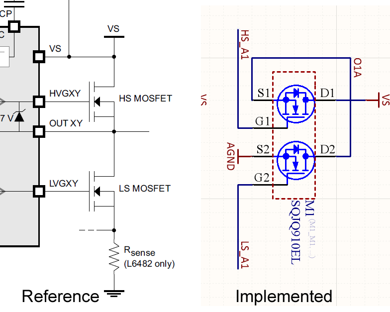
The driver IC uses external dual mosfets: SQJQ910EL-T1_GE3. I have blank PCBs from the manufacturer so that I can test any net for continuity. So far everything check out. I’ve looked over the pcb layout in cad, and can’t find any obvious problem with the output stage. I have checked the resistance between the output pins and GND/VS; the resistance is approaching 1 MOhm, except in one case where I think the multimeter was turning the mosfet gate on, because it was reading 7KOhm with the black lead on GND and the red lead on the pin but not when I reversed them.
How would I go about determining what is wrong with driver, given my available tools? (The scope, the meter and the blank pcbs).
Any vauge advice would be helpful.
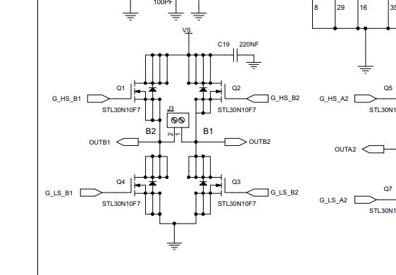
Can you show the schematic for the output driver stage?
Are you sure you have the winding’s in the correct order? Does it looks like if might be stepping forward and then back? If the wiring is wrong, stepper motors won’t turn.
How are you powering this? If a bench supply and not enough current to drive the motor, you will see the supply voltage drop so it doesn’t sound like a current issue as you are still seeing good voltage.
I’m pretty sure about the phases. I even double checked just now 'cause you mentioned it. It doesn’t feel like it’s just vibrating in place. I was full stepping, and I know those motors. They should feel a lot stronger than that.
I’m powering it from a ATX PSU. Probing the VCC pin showed that the voltage max was 13.1 and min was 11. something. Average was 12.1V.
my go-to test here would always be the L6480 module I’d been using in early tests, putting my code against that so I know if it behaves differently to the new hardware… edit: but I know these are non-trivial little beasts so that may not be 1:1 pointing to software/driver issue versus configuration issue in what your software tells it to do…
N Channel Mosfets need to be connected to GND with sufficient current to be able to turn off right? Therefore if the driver IC isn’t able to turn them off then when I scope the mosfet on the high side it’s source voltage should be VCC right? (i.e. 12.1 Volts from the power supply). I noticed that when the chip is in stand by that motor output drops to GND, but when I take the device out of stand by and before I issue any command it goes to VCC. I think I’ll check this will a 12v led. If the led is on then current is flowing but the drive should still be in HiZ state (motor outputs off).
The IC says it provides from 4ma to 96ma of gate current to support a wide array of mosfets. Could it be that I choose the wrong value mosfets, and those need a higher gate voltage to turn off?
I attached some 12V leds to the output pins. I also tested them on a 9v battery. They shone way brighter on the 9V battery. Also they don’t turn on when the motor is at HiZ.
Yes, the pcb engine used the eval board’s schematic and layout as reference (at least he was told to). From comparing them myself I can’t see any obvious differences.
So next step for me is to get an eval board? I wanted to get the board that came with the STM32 on it so that I can plug in values on the workstation and have it just work, but I could not find any sellers.
There is a charge pump that is used to generate the higher voltage needed to switch off the MOSFET’s. This has to be configured so that the voltage is higher than the supply to ensure that the MOSFET’s are switched off.
Is this configured correctly in your design? What is the voltage at VBOOT?
I will have to add a short wire to the VBOOT net (on one of the passives) to find out. While the soldering iron is hot, are there any other voltages I should be probing?
EDIT: Btw, what voltages should I be looking for on the gate? If it’s 18V or more then that means the gate is off? If it’s less than 12 then the gate is on?
Ok, from the application note under the topic 2.4 Wrong setup issues
Starting from VCC the gate voltage is decreased down to the Miller plateau region, but the gate charge is not enough to complete the plateau and the Miller clamp is closed before the Vds commutation is ended. The MOSFET is immediately turned off and as a consequence the output of the power stage is subjected to a strong slew rate which could cause critical issues.
In the second case the gate charge is not enough to complete the Miller plateau region (see
Figure 12). In this case the output commutation is not completed and the overcurrent
protection, which measures the voltage drop on the MOSFET, is triggered even if very low
or even no load current is present.
The document itself is about the setup of the system to suit the selected MOSFETS, however they don’t give an actual example! (and I don’t understand).

 I wanted to get the board that came with the STM32 on it so that I can plug in values on the workstation and have it just work, but I could not find any sellers.