Wiznet W5500 Example throw exception

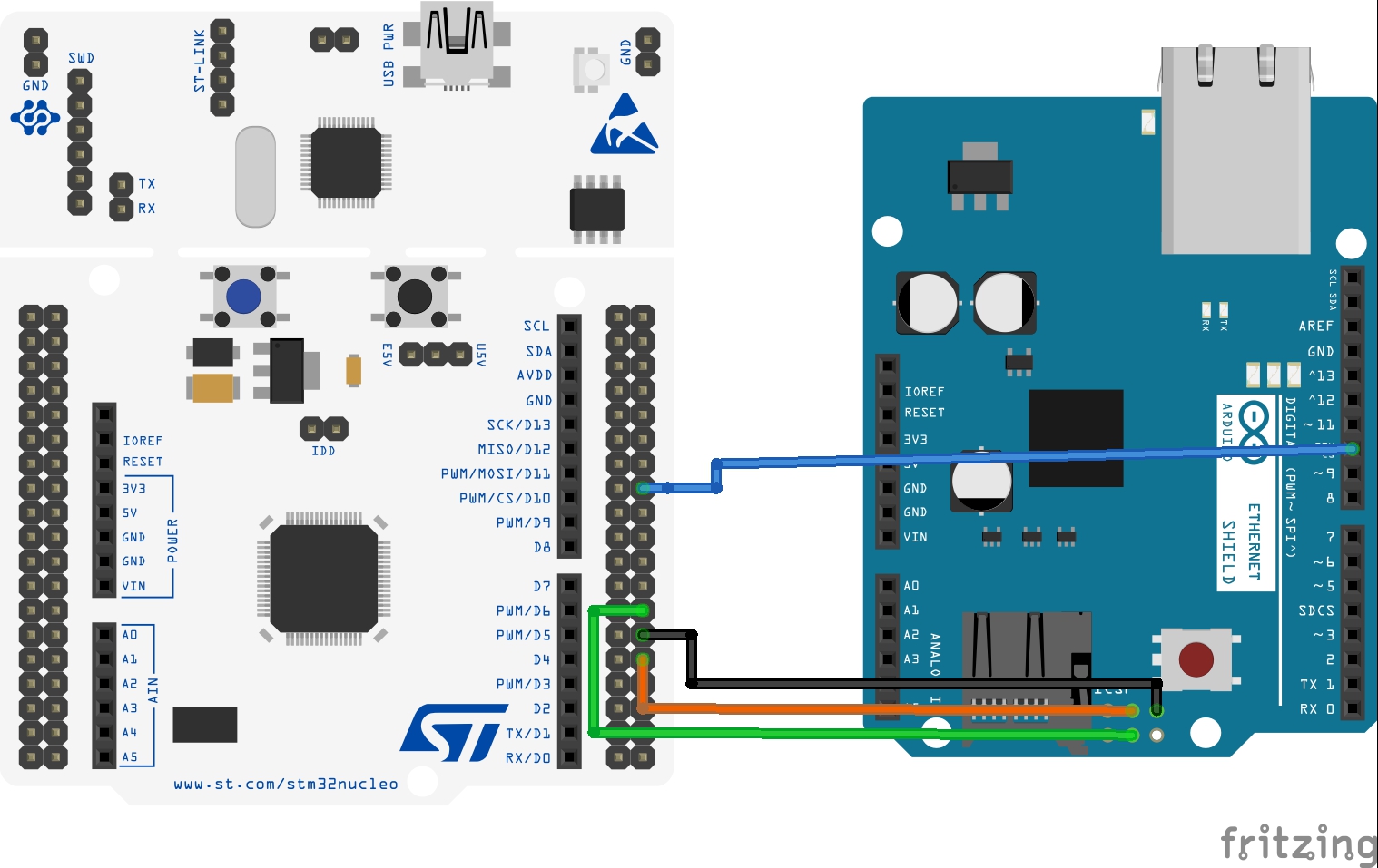
I’m trying to update an old product that a client wants more of. The old product used a FEZ Panda II and a GHI Ethernet Shield.

I’m attempting to replace it with a Fez Duino and a standard Arduino Ethernet shield (W5500). The device software and TinyCLR installs are all current. To debug,m I’ve removed the Nuget W5500 driver and used the source from GitHub.

My pin declarations and initialisation code is:

var cs = GpioController.GetDefault().OpenPin(SC20100.GpioPin.PB1);          // Arduino D10 - Correct for Arduino SPI CS
var reset = GpioController.GetDefault().OpenPin(SC20100.GpioPin.PC4);       // Arduino D7
var interrupt = GpioController.GetDefault().OpenPin(SC20100.GpioPin.PA15);  // Need to find a pin for this. Standard ethernet shields don't support IRQ
var spiController = SpiController.FromName(SC20100.SpiBus.Spi6);            // Arduino D11, D12, D13

var networkController = new W5500Controller(spiController, cs, reset, interrupt);

The throw new Exception("Insufficient buffer space available"); exception is thrown in the following code in W5500Driver.cs :

internal int WriteData(int slot, ref ushort ptr, byte[] src, int offset, int len)
        {
            if (len > this.memsize)
                throw new Exception("The size of the payload exceeds the socket memory size of " + this.memsize + " bytes");
            var freeSize = this.SocketRegisterReadUshort(SocketRegisters.TX_FSR, slot);
            if (len > freeSize)
                throw new Exception("Insufficient buffer space available");

            this.buffer[0] = (byte)((ptr >> 8) & 0xff);
            this.buffer[1] = (byte)(ptr & 0xff);
            this.buffer[2] = (byte)(this.SocketTxRegisterBlock(slot) | SPI_WRITE);
            Array.Copy(src, offset, this.buffer, 3, len);
            this.WriteRead(this.buffer, 0, len + 3, this.buffer, 0, 0, 0);
            ptr += (ushort)len;

            return len;
        }

The var freeSize = ... line is asking the WizNet chip how much free memory it has left in that particular socket (slot). The len that you are trying to send exceeds that size, but is apparently smaller than the total available memory for that slot, meaning that it would have fit if only something else wasn’t there already. ‘something else’ meaning bytes from a previous send or an ongoing receive.

There are three possible solutions:

  1. Reduce the number of sockets that was configured when the W5500Controller was created. This is the fifth argument in the constructor for W5500Controller, and it defaults to 8. You could set it to 4 and that would double the amount of memory that you have available per socket, but will still allow you to have four sockets open at the same time. Note that this value has to be a power of 2 (1, 2, 4, 8, …)

  2. Wait for whatever send or receive is in progress to complete and free up the buffer before you start this send.

  3. Send data in smaller chunks.

Thanks. Yep, I know it’s after the free size, and it’s getting zero back. I was really hoping I wasn’t going to have to debug the GHI Wiz5500 drivers. I’m in the process of doing that. The code hasn’t sent anything - this is right in the initialisation code of their example on their website. The only thing that has been sent to the chip is a soft reset command at this point.

The one thing that looking at the code has made clear is that the reset and interrupt lines aren’t needed, so I’ve changed them both to null. Some documentation would sure be nice.

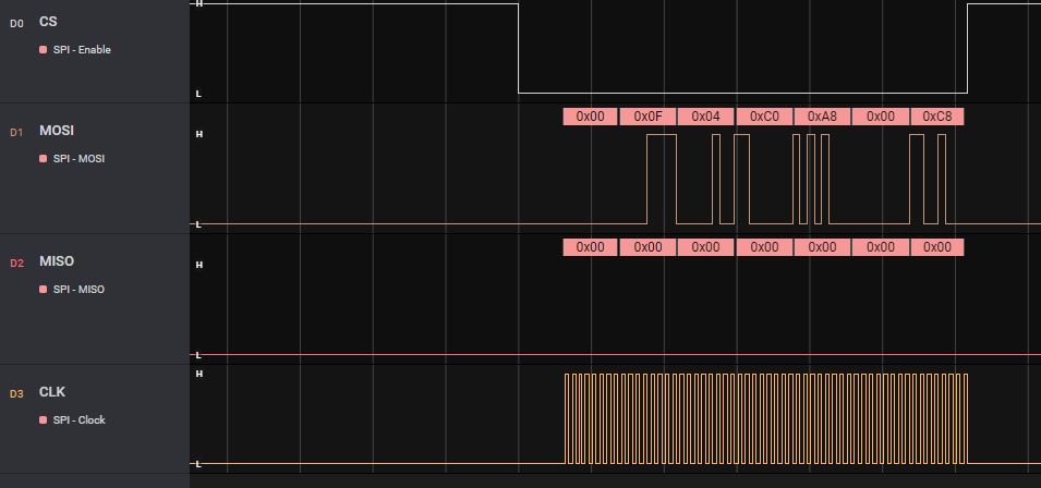
Pulled the logic analyser out and the MISO pin is stuck low. Happens with multiple W5500 shields, so it’s either hardware on the Fez Duino or a psuedo-hardware issue like a misconfiguration of the SPI module pins. Sigh. Much debugging for what was supposed to be a quick and dirty port. No wonder I keep losing money…

as far i know W5100 and W5200 and W5500 Arduino Shields
suffer from RESET issues and try different “no arduino shield” or fix this shields “on power up and can hang it on spi mode”

SOLUTION - Arduino w5100 ethernet shield won’t reset upon power-up - YouTube

Thanks, I wish it was that simple, but I’ve been mashing the reset button many times while debugging. Something I’ll watch out for in future.

Well, I guess I’m stuck. The SPI implementation is down in the weeds, so I can’t see the PIN selection definitions. If any GHI person reads this, here’s what my logic analyser sees on the SPI lines. Note that this is with multiple boards, and I’ve checked for shorts on the FEZ Duino board, that checks OK.

And here is code, a lightly modified version of your demo app for the W5500 driver:

using GHIElectronics.TinyCLR.Devices.Gpio;
using GHIElectronics.TinyCLR.Devices.Spi;
using GHIElectronics.TinyCLR.Drivers.BasicNet.Sockets;
using GHIElectronics.TinyCLR.Drivers.BasicNet;
using GHIElectronics.TinyCLR.Drivers.WIZnet.W5500;
using GHIElectronics.TinyCLR.Pins;
using System;
using System.Collections;
using System.Diagnostics;
using System.Text;
using System.Threading;

namespace TinyCLRApplication2
{
    internal class Program
    {
        static void Main()
        {
            GpioPin cs = GpioController.GetDefault().OpenPin(SC20100.GpioPin.PB1);          // Arduino D10 - Correct for Arduino SPI CS
            GpioPin reset = null; // GpioController.GetDefault().OpenPin(SC20100.GpioPin.PC4);       // Arduino D7
            GpioPin interrupt = null; // GpioController.GetDefault().OpenPin(SC20100.GpioPin.PA15);  // Need to find a pin for this. Standard ethernet shields don't support IRQ

            SpiController spiController = SpiController.FromName(SC20100.SpiBus.Spi6);            // Arduino D11, D12, D13

            W5500Controller networkController = new W5500Controller(spiController, cs, reset, interrupt);
            bool isReady = false;

            networkController.NetworkAddressChanged += (a, b) =>
            {
                isReady = networkController.Address.GetAddressBytes()[0] != 0 && networkController.Address.GetAddressBytes()[1] != 0;
            };

            NetworkInterfaceSettings networkSettings = new NetworkInterfaceSettings()
            {                 
                Address = new IPAddress(new byte[] { 192, 168, 0, 200 }),
                SubnetMask = new IPAddress(new byte[] { 255, 255, 255, 0 }),
                GatewayAddress = new IPAddress(new byte[] { 192, 168, 0, 1 }),
                DnsAddresses = new IPAddress[] { new IPAddress(new byte[] { 75, 75, 75, 75 }), new IPAddress(new byte[] { 75, 75, 75, 76 }) },

                MacAddress = new byte[] { 0x02, 0x01, 0x02, 0x03, 0x04, 0x05 },
                //DhcpEnable = true,
                //DynamicDnsEnable = true,
                Hostname = "KenoInterface"
            };


            networkController.SetInterfaceSettings(networkSettings);
            try {
                networkController.Enable();
            } catch (Exception ex) { 
                Debug.WriteLine($"Exception : {ex.Message}\r\n"); 
            }

            while (isReady == false) ; // wait for valid IP address. 

            var dns = new Dns(networkController);
            var host = dns.GetHostEntry("www.example.com");
            var ep = new IPEndPoint(host.AddressList[0], 80);

            // Streaming socket
            var socket = new Socket(networkController, AddressFamily.InterNetwork, SocketType.Stream, ProtocolType.Tcp);
            socket.Connect(ep);


            var content = "GET / HTTP/1.1\r\nHost: www.example.com\r\nConnection: close\r\n\r\n";
            socket.Send(Encoding.UTF8.GetBytes(content));

            var received = socket.Receive(SocketFlags.None);

            if (received.Length > 0)
            {
                var recvdContent = new string(Encoding.UTF8.GetChars(received));
                Debug.WriteLine("Received : \r\n" + recvdContent);
            }
        }
    }
}

your board doesn’t need reset and interrupt pins?

Arduino W5500 shields don’t have either.

As @valon_hoti_gmail_com mentioned, I think there is something with reset issue on the shield.

From your post, MOSI is sending as well, MISO is something that belong to the shield.
Nothing relates to network here yet.

The shield need to be wakeup, interrupt line, power reset sequences…

Does this shield work on other devices? what is supposed to see on MISO line when master send those bytes above?

are those very first bytes or you just capture randomly?

And, how did you get the MAC address? use tool to generate or pick random bytes?

Does the shield response any data or just 0x00 at all the time?

1 Like

hope this doc

and

and hope somehow help something …

i don’t know what kind of shield you have …

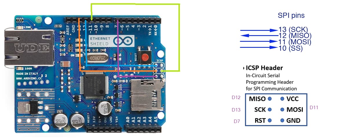
but in arduino you need to trigger 5v on shield to work (or have selector 3.3v with 5v) and pins for SPI to have proper connections from D10,D11,D12,D13

as is on tutorial
https://docs.ghielectronics.com/software/tinyclr/tutorials/spi.html

var cs = GpioController.GetDefault().OpenPin(SC20100.GpioPin.PB1);

var settings = new SpiConnectionSettings() {
    ChipSelectType = SpiChipSelectType.Gpio,
    ChipSelectLine = cs,
    Mode = SpiMode.Mode0,
    ClockFrequency = 80_000_000,
};

var controller = SpiController.FromName(SC20100.SpiBus.Spi6);
var device = controller.GetDevice(settings);
1 Like

Forget it. I forgot something critical - the Arduino Ethernet shields use the ICSP connector for the SPI port for the Wiz5100. Sigh. I got caught out as the original product used the Panda II board and the GHI Ethernet shield, which used Arduino D10-D13 for the Wiznet chip. These only connect to the SD card on an Ardunio shield. Back to the drawing board.

1 Like

just create bridge from pins D13 D12,D11 to ICSP headers (SPI) similiar to pictures

or check this post

https://dave.cheney.net/2014/07/13/arduino-spi-woes

Hi @valon_hoti_gmail_com , why is it 80_000_000?

Should it be 8MHz?

:flushed: i don’t know what clock is used for Wiz5500

i refer to doc

page 2 “it state it support 80 mhz” → maybe i’m wrong something …

Thanks, I was just curious if this is something special has to be for the shield.

Because when i tested with click board and 4MHz seems fine, never tested on arduino shield.

1 Like

try to create cross wire connection D pins with ICSP headers