It would be quite useful to use a SC20 or SC13 as a USB serial port while maintaining the USB debugging functionality.
I am in no means an expert on USB, but I have seen that the Teensy boards can pull something like this off. They are connected as a generic USB device for programming, but you can configure them to also show up as a serial port. You can even go as far as three serial ports from that 1 teensy over 1 usb cable!
This would be useful because then we can connect over a very standard way with the sitcore while maintaining the option to debug over USB. Otherwise I would have to sacrifice one of the UARTs, add an FTDI of some sort and add a second USB port to the product.
My use case here is configuration and software updates in a user friendly way trough a small windows forms app. I would like to be able to do this trough the same USB port as I would use to program and debug the sitcore.
With my limited understanding of USB, I think this would mean that the sitcore would broadcast out two device descriptors? The one we already have to debug the board and another one that is a USB serial port. Accessing this trough sitcore would be similar to using a UART.
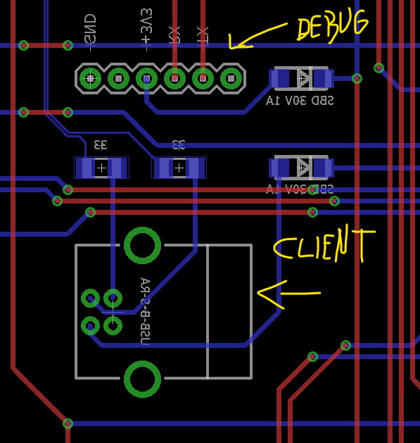
And i use this cable (has FTDI inside) for debugging, no need for FTDI chip on every PCB.
The client can connect with USB (B in my case because its more sturdy)
I like it this way, less of a chance for clients to mess with anything, they don’t usually have the cable for serial debug.
I usually leave my debug output always on, and without a cable they cant see anything.
If you are going to use USB on your PCB, be sure to follow the differential pair rules required for it otherwise you will have timing issues. Keep the lengths as close to being the same and make sure they don’t exceed the max difference allowed. Track width and spacing are critical for a reliable USB connection. The longer your traces are, the more you have to take care of the rules.
I see it but the traces look very thin and too close to meet the differential specs for USB. One track also looks much longer. I just mention this as my first time with USB i made the mistake of not following the rules and had issues. Now that I follow them, USB has been super stable.
 I just mention this as my first time with USB i made the mistake of not following the rules and had issues. Now that I follow them, USB has been super stable.