as far i now STM32F411xxx have just 512 kb - with 128 kb
WIFI have other “but is not included” so port for ==> Nucleo F411RE
should work
so you just need to set up your pins properly and crystal clock properly
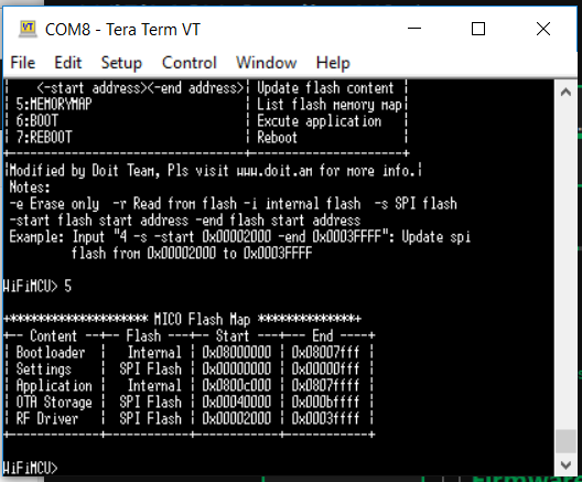
no just you need to flash on address 0x08000000 as bootloader (since TinyCLR include bootloader)
so SPI flash need to be used as storage (like SD CARD - USB FLASH …,with apropriate drivers or need to create them)
You need to see how to access with st-link
or
usart1(pa9,pa10)or usart2(pa2,pa3) or usart6 (pa11,pa12)
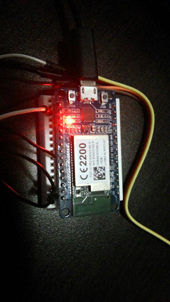
But how i see on doc as i described above you have access on pa11,pa12 (if those pins are 5v tolerant no need for ttl converter from 5v to 3.3v)so cut an usb (another part you do not use for pc) and use (an ttl converter from 5v to 3.3v)
Usb Green wire connect [to ttl converter (5v pin) another one of ttl converter (3.3v pin)] to pin 27 on mcu
Usb White wire connect [to ttl converter (5v pin) another one of ttl converter (3.3v pin)] to pin 35 on mcu
Usb black wire (
of Gnd pin on ttl converter gnd which you) connect on mcu gnd
Red wire 5v No need to use
To enter on Dfu mode you should need to connect pin boot0 and vcc(3.3v) with an jumper
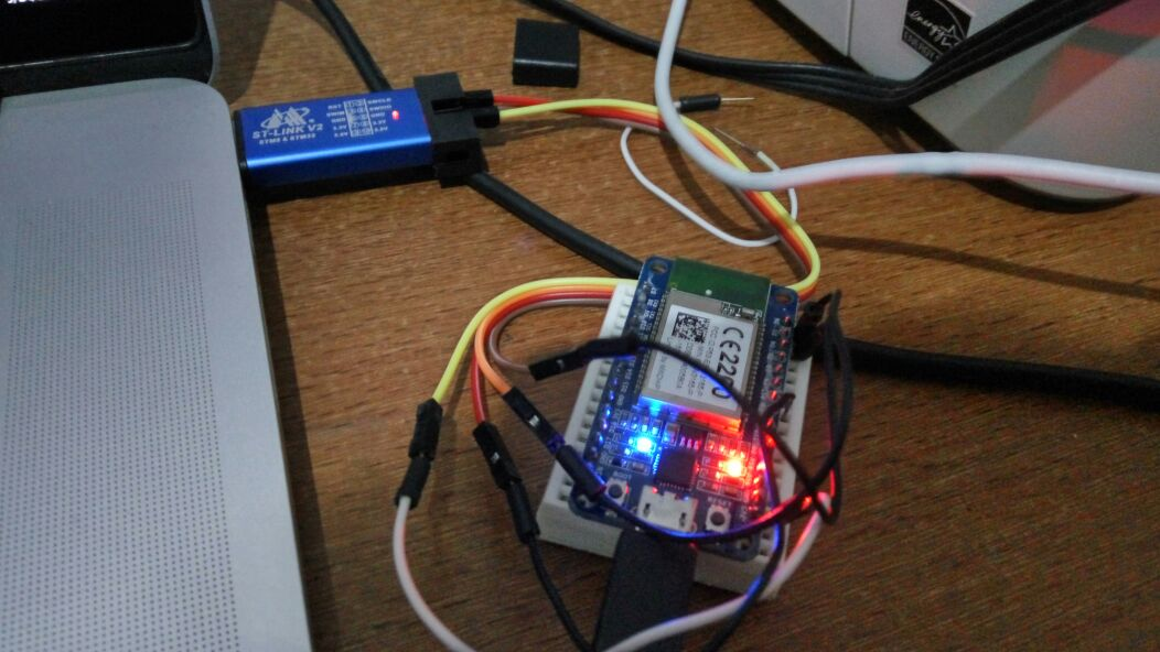
First, I can’t find BOOT0 so I cannot enter DFU mode. So, I try to use ST-LINK V2 to erase and flash the new firmware (.bin). I use the same file with NUCLEO-F411RE, but I change “SYSTEM_CRYSTAL_CLOCK_HZ” to 26 Mhz in deviceselector.h
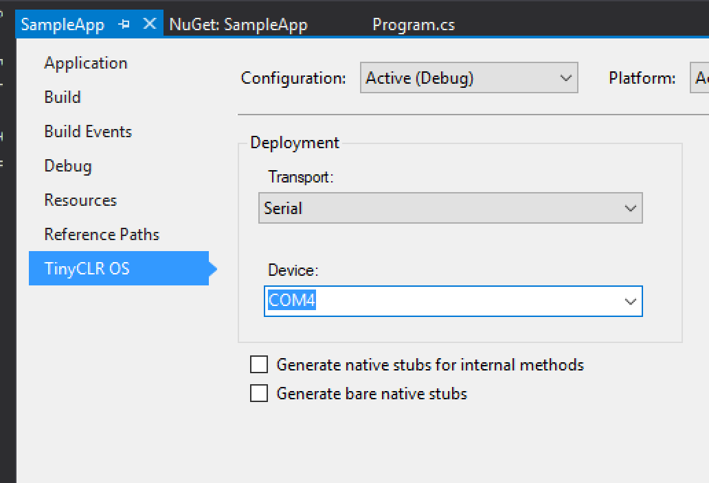
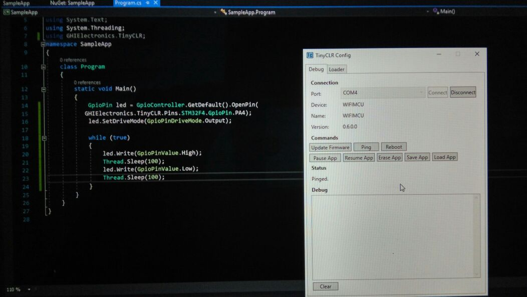
it has CP210X, so in Visual Studio you should change transport to Serial and select a correct COM port.
One thing you may find easier is to start with the device ports in the dev branch. We’ve made a lot of improvements from what is currently in master. The device selector file should be a lot easier to use, modify, and understand now.