I’m trying to run a Netduino 3 WiFi and the Gadgeteer Serial Camera L1 module. Before deciding that it is not possible to manage the connection via GoBus, I came across some API inconsistencies.
mscorlib (0.6.0) contains the definition of the Buffer class: I have found an example of how to write and read from the module stream, but it seems that the examples refer to a different version of the various libraries (http: //old.ghielectronics. com / community / forums / topic? id = 24134).
the only public constructor accepts a parameter relative to the overall size of the array;
// Methods
[CLSCompliant(false)]
public Buffer(uint capacity)
{
this.data = new byte[capacity];
this.offset = 0;
this.length = 0;
this.Capacity = capacity;
}
internal Buffer(byte[] data, int offset, int length, int capacity)
{
if (data == null)
{
throw new ArgumentNullException(“data”);
}
if (offset < 0)
{
throw new ArgumentOutOfRangeException(“offset”);
}
if (length < 0)
{
throw new ArgumentOutOfRangeException(“length”);
}
if (capacity < 0)
{
throw new ArgumentOutOfRangeException(“capacity”);
}
if (((length > capacity) || ((data.Length - offset) < length)) || ((data.Length - offset) < capacity))
{
throw new ArgumentException();
}
this.data = data;
this.offset = offset;
this.length = (uint) length;
this.Capacity = (uint) capacity;
}
the variable that contains the data is internal and not accessible using the only available manufacturer;
public sealed class Buffer : IBuffer
{
// Fields
internal byte[] data;
…
it is not possible to prepare a new class that implements IBuffer since the Write executes a specific cast to the Buffer class and not to IBuffer → InvalidCastException.
Does anyone know an easy way to read / write to the module stream with the current version of the API?
The easiest way is to use the DataReader and DataWriter classes in GHIElectronics.TinyCLR.Storage. Their constructors take an IInputStream and IOutputStream. You can find an instance of each of those at SerialDevice.InputStream and SerialDevice.OutputStream. You can find a basic example of using it in the docs.
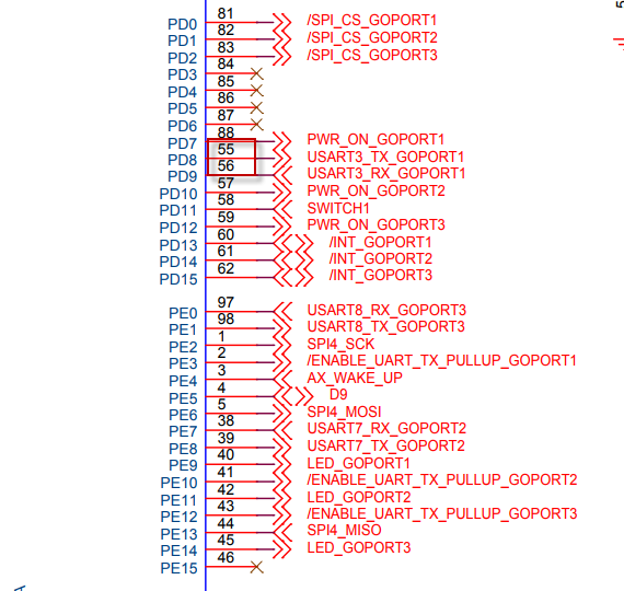
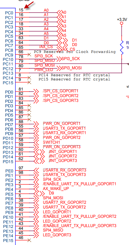
Pin definition.
public const int Pin3 = STM32F4.GpioPin.PD13;
/// Pin definition.
public const int Pin4 = STM32F4.GpioPin.PD8;
/// Pin definition.
public const int Pin5 = STM32F4.GpioPin.PD9;
/// Pin definition.
public const int Pin6 = STM32F4.GpioPin.PD0;
/// LED definition.
public const int Led = STM32F4.GpioPin.PE9;
/// Power On definition.
public const int PwrOn = STM32F4.GpioPin.PD7;
}
from GHIElectronics.TinyCLR.Pins.dll (STM32F4 class)
public const int PD0 = 0x30;
public const int PD1 = 0x31;
public const int PD10 = 0x3a;
public const int PD11 = 0x3b;
public const int PD12 = 60;
public const int PD13 = 0x3d;
public const int PD14 = 0x3e;
public const int PD15 = 0x3f;
public const int PD2 = 50;
public const int PD3 = 0x33;
public const int PD4 = 0x34;
public const int PD5 = 0x35;
public const int PD6 = 0x36;
public const int PD7 = 0x37;
public const int PD8 = 0x38;
public const int PD9 = 0x39;
If I am understanding you correctly, the number next to the schematic symbol is just the physical pin number on the processor, not pin name converted to an integer, that’s purely a NETMF convention. PD8 is properly ((4 - 1) * 16) + 8 = 56 = 0x38.
But it looks like you’re saying pins 3 and 4 on GoPort1 should be PD6 and PD7, not PD8 and PD9?
But I would like your confirmation. In any case I tried to manually alter the mapping as expected and I correctly detect a UART transmission … also if that module can not properly work on board with less than 1Mb.