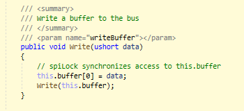
I previously had a design with a G400 controlling an AD9833 via SPI. With .NET micro, the SPI write buffers were in the form of ushorts and worked well with this chip (requires 5 successive 16 bit words for initial programming).
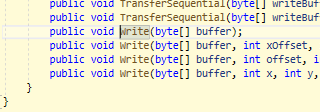
With the SCM20260, I am unable to get this chip to recognize commands, and believe it may be due to the write buffer size but am definitely not an expert here. Does anyone have any experience with this chip and TinyCLR, and if so, would you be willing to share a code snippet for your settings and write set-up.
I’ve tried modes 0 - 3, and the chip seems to respond to 0x2100 (reset) with modes 0 and 3 (see blip in output on o-scope), but does not receive other commands. Modes 1 and 2 have no effect.
I’ve also attempted to set the chipselecttype to none and toggle the CS bit myself to no avail.
@jwilmoth
humor me and take control of the CS line and set/reset it between each write.
Im not sure what the spi controller tries to do with the CS line when you give it control, which is why i personally dont use it.
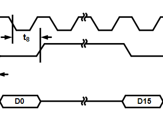
fwiw appears this AD9833 device requires it between words:
so unless you tell me otherwise, ill assume you need to ensure its happening
You are thinking I should do something like this? If so, I gave this a shot and still didn’t work (Also tried single write command each time with two bytes of data). Next step I’ll check out the CLK and MOSI signals on an o-scope and see if they match what I’m trying to send.
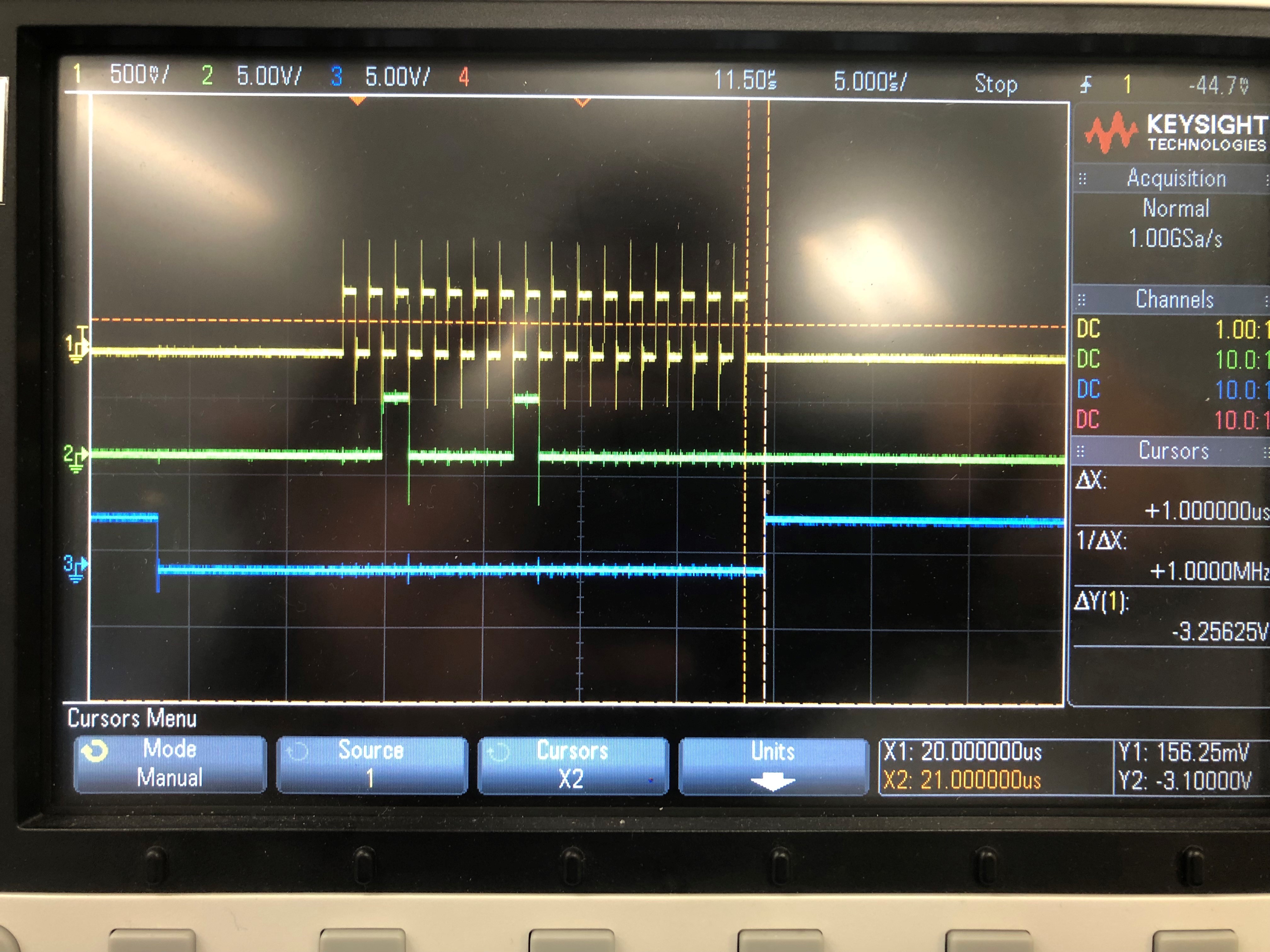
Hi Guys, new update: I was able to pull up the SCK, MOSI, and CS signals on an oscope (see below). Per the datasheet, the 9833 says:
“The SCLK can be continuous, or it can idle high or low between
write operations. In either case, it must be high when FSYNC
goes low (t11).”
In the oscope image, the top trace is the SCK signal, the middle trace is MOSI, and the bottom trace is CS. Notice that CS falls while the SCK signal is low, which contradicts what the AD9833 requires per the quote above.
Previously with .NET micro, there was a parameter in the configuration for clock idle state that does not exist in TinyCLR. I’m thinking this is the reason the chip isn’t recognizing the commands. Thoughts or suggestions on changing the clock idle state?
@Gus_Issa Yes I’m with you just wasn’t sure how the system approached writing 8 bit segments vs. 16 bit segments. Based on the o-scope, it looks like it writes these in a continuous mode so both should be equivalent, with the exception of the clock idle state I mentioned above.
Clock idle is still valid and correct during days transfers but for whatever reason I remember ST didn’t handle it nicely outside active transfers. Maybe it has to do with multi master support.
I am going off what I remember from 2 years ago so I could be wrong.
@Gus_Issa I am not sure exactly what that means. Is there a way for me to correct this using built in libraries, or do I need to find some other work around?
I tried adding a pull-up to the sck line, but it looks like it must be a push pull clock, so still held the line low.
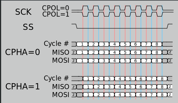
it seems that you need CPOL=1 using mode 2 or 3. I only mention this as your sample stated you were trying to use 0
Mode = SpiMode.Mode0
(and i see it in your scope output is either using mode 0 or 1)
CPOL=1 is a clock which idles at 1, and each cycle consists of a pulse of 0.
That is, the leading edge is a falling edge, and the trailing edge is a rising edge.
I dont think there is enough info to determine what CPHA should be, perhaps its in the spec sheet
Here you can see when using mode 2 or 3 CS can go low when clock idle is high
@axa Really appreciate that. You were right the mode was incorrect. It seems the coms is working now (intermittently, but better than before). I currently have this set up on a breadboard with terrible wiring, so hopefully once I get the actual prototype in, it will work better.