The library is a port of techfoonninja’s Windows 10 IoT core library, which was a port of Gralin’s netMF library and over the last 8 years the library has collected some “baggage” so I’m thinking about doing a V2 version.
Yes, I know it’s a stupid idea to start again but with covid-19 things have been a bit quiet.
A few months back, I think it was around June I spotted your work on getting the tinyCLR dev boards working with the nrf24L001 so figured I had a couple that I’ve used with MSP430’s and Arduinos just fine, but for the life of me I couldn’t get them communicating with the SC20100 connected to a nrf trx device. Mind you I don’t have a MikroBus device, so I had to wire it through the pins on the nrf device that I have. Would love to know if there are any pointers in terms of debugging on this. I believe I have it all connected correctly as the moduleSPI program seemed to work(output wise).
I would start with the ModuleSPI code in the github repo (have just added config for the port on the Fezportal and both on the SC20100 dev) with that you should be able to check your SPI port configuration.
Your SPI port setup (MISO, MOSI, CS & SCLK pins) is most probably good if the output looks like below…
The length setting is most obvious one it should be 5.
The thread ‘’ (0x2) has exited with code 0 (0x0).
nrf24L01Device Device…
ConfigureSpiPort Done…
Read address width
nrf24L01Device.TransferFullDuplex…SETUP_AW
txBuffer:03-00
rxBuffer:0E-03
Address width 0x03 - Value 0X03 Value adjusted 5
RF Channel read 2
nrf24L01Device.TransferFullDuplex…RF_CH
txBuffer:05-00
rxBuffer:0E-03
RF Channel 2 0x05 - Value 0X03 - Value adjusted 2403
If that is ok, I would then fire up the TinyCLRV2nRF24Client and put a breakpoint on the while(true) around line 85 and check that the configuration read back matches what is set (try changing the power level).
If that works then your chip enable(CE) config is most probably good.
If you’re not getting any Radio_OnDataReceived, Radio_OnTransmitSuccess or Radio_OnTransmitFailed notifications then it’s most probably the interrupt pin config.
That’s how I would debug setup…
Other users might find this useful so i’ll add it to the Github readme
So the output values on the Modulespi program were pretty much spot on. I had changed the values for RF_CH and P0_Address to match the ones that I used for the client program.
On the client, I included the result of the status method as well.and values.
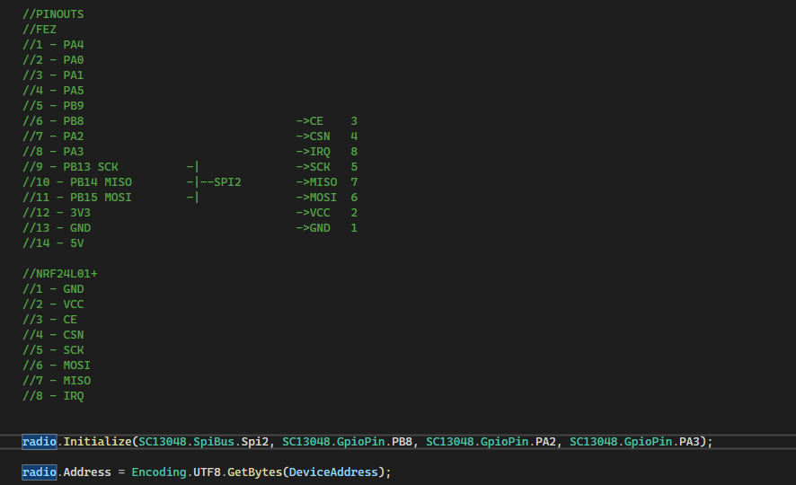
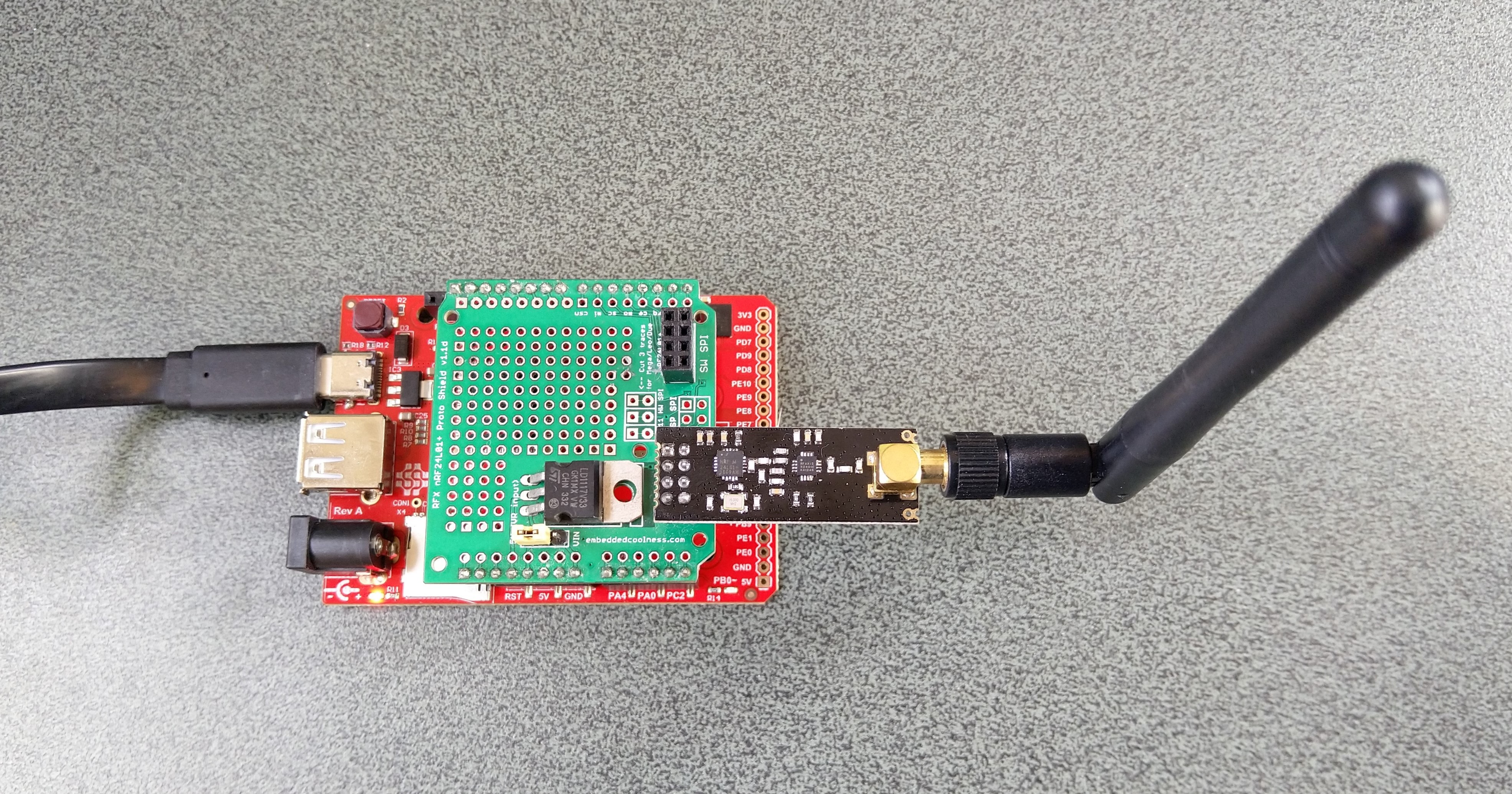
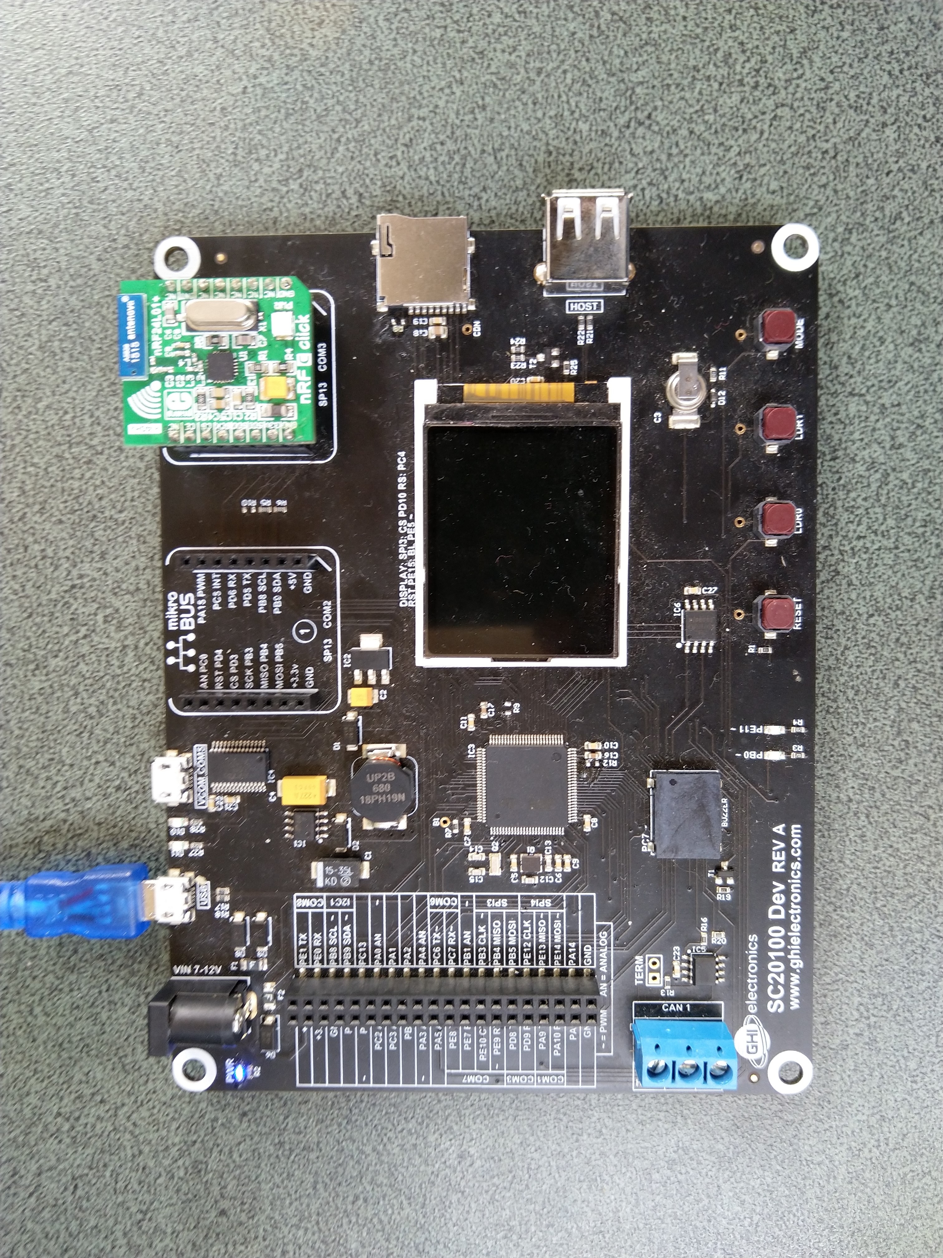
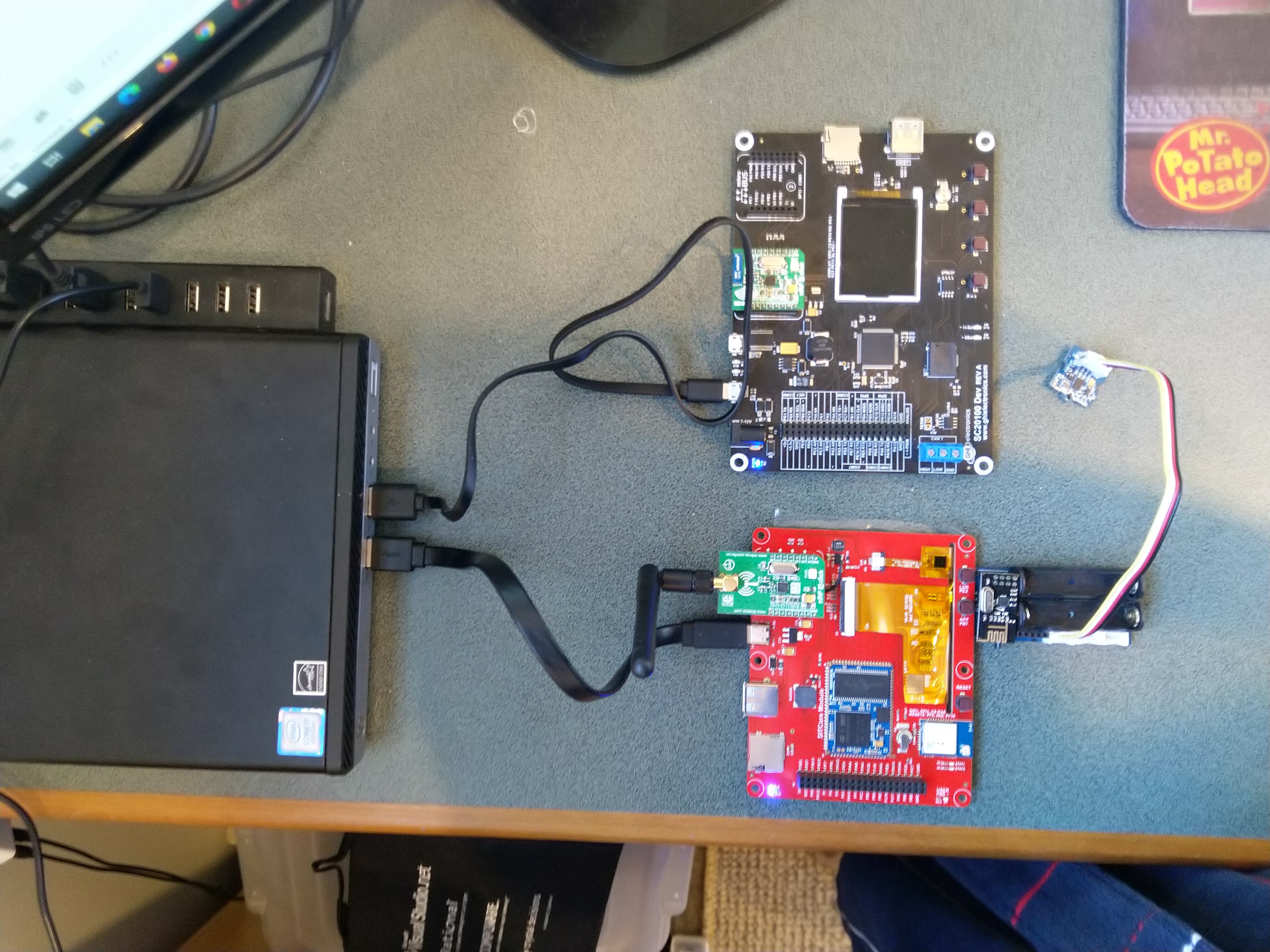
This is the setup.
Forgot to add the device that I’m using but they look like these.
Now, to be clear, I have some that I suspect are the Si24R1 but I also have a pair of legit nordic Trx devices that I also have tested and were unsuccessful with.
I could receive messages from my devDuino configured like this
// nRF24L01 ISM wireless module setup
RF24 radio(7,6);
char payload[] = "devDuino";
const byte FieldGatewayAddress[5] = "NODE1";
const byte FieldGatewayChannel = 0x78 ;
const rf24_pa_dbm_e RadioPALevel = RF24_PA_MAX;
const rf24_datarate_e RadioDataRate = RF24_250KBPS;

const int LoopSleepDelay = 5000 ;

void setup()
{
  Serial.begin(9600);
  Serial.println("Setup called");

  // Configure the nRF24 module
  Serial.println("nRF24 setup");
  radio.begin();
  radio.setPALevel(RadioPALevel);
  radio.setDataRate(RadioDataRate) ;
  radio.setChannel(FieldGatewayChannel);
  radio.enableDynamicPayloads();
  radio.openWritingPipe(FieldGatewayAddress);

  delay(5000);

  Serial.println("Setup done");
}

void loop()
{
  Serial.println("Loop called");

  // Powerup the nRF24 chipset then send the payload to base station
  radio.powerUp();
  delay(500);

  Serial.println( "nRF24 write" ) ;
  boolean result = radio.write(payload, sizeof(payload));
  if (result)
    Serial.println("Write Ok...");
  else
    Serial.println("Write failed.");

 Serial.println( "nRF24 power down" ) ;
 radio.powerDown();

 delay(LoopSleepDelay);
}
Most probably something todo with the pipe setup, don’t have time to drill deeper this AM will have a look this PM. Vague memory it’s something todo with multicasting…
Awesome! that got me receiving data from the Devduino code. This should give me a starting point to hopefully get the MSP430’s working.
So far I’ve noted two issue with my original code that had an affect on this working. One was how I was defining the address. The other was a crc setting which I know I had set when testing this a while back.
hopefully now I can get some 2 way communication going!
The design of the Gralin library was “inspired” by one of the popular Arduino libraries. Techfooninja then ported (though I sometimes wonder if he started with mfNordic library) it to Windows 10 IoT Core. Then I have ported it to Meadow, nanoFramework & TinyCLR.
The core of the implementation is quite “arduinoy”(can’t think of a better term) and over the last 9 years cruft has accumulated.
As per my initial post I was thinking about starting again and doing a version that could be built for the embedded .Net platforms TinyCLR, Meadow, nanoFramework, Windows 10 IoT Core (not like anyone cares) and .Net Core on *nix.
I know starting again from scratch is a usually a dumb idea, but after a number of ports and debugging issues I have a plan…
Would anyone be interested in helping with testing etc.
The only thing I would disagree with is to make some kind of “universal driver”. Each OS has its own particularities and dealing with those in a single driver may either complicate it or make it bigger than needed.
Although size does not matter here (for once ) , since we have plenty of memory. But still.
Noob question: Has anyone gotten this to work withe the FEZ Flea? I can get the sample app compiled and running on the device but when it sets the Radio.Address property the value doesn’t stick. It’s within the 3-5 character range, but reading back just returns 0s from the register. I’m thinking maybe I have the pins wrong?

 ) , since we have plenty of memory. But still.