Hello,
I was playing with a FT810 chip on the SC20260 dev board and I’ve found that I could not go as fast as I should with this module.
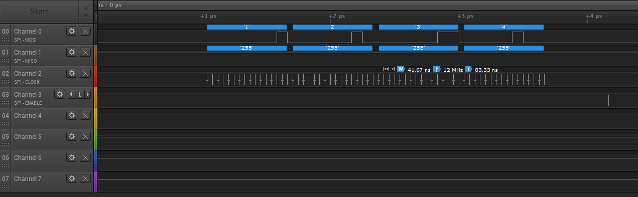
It’s given for 30MHz max but, depending on the SPI bus I choose, I can only go at 12MHz max 
The FT810 has to be initialized with a SPI frequency below 10MHz. So I’m using 2MHz to be (really) safe during initialization.
Then, at the end of the init process, I raise the frequency to the maximum allowed, or not so far given the prescaler results. This should be somewhere around 21 or 24MHz, I think.
Anyway, I can only go to 12MHz on SPI5 (although it is given for 60MHz max) and 8Mhz on SPI2 & SPI3 (which are given for 24MHz max).
The following code does reproduce the issue. It simply reads the chip ID twice : once at the beginning of the init process and another time once the init process is over and I can raise the SPI frequency.
using GHIElectronics.TinyCLR.Devices.Gpio;
using GHIElectronics.TinyCLR.Devices.Spi;
using GHIElectronics.TinyCLR.Pins;
using System;
using System.Diagnostics;
using System.Threading;

namespace SPI_Issue
{
    class Program
    {
        static void Main()
        {
            new FT810(SC20260.SpiBus.Spi3);

            Thread.Sleep(Timeout.Infinite);
        }

    }

    public class FT810
    {
        private readonly SpiDevice _ft800;
        private readonly GpioPin _rst;
        private UInt32 RAM_REG;
        private readonly String _spiBus;

        private readonly Byte[] FT8XX_REG_PCLK = new Byte[] { 0x6C, 0x70 };
        private readonly Byte[] FT8XX_REG_PCLK_POL = new Byte[] { 0x68, 0x6C };
        private readonly Byte[] FT8XX_REG_CSPREAD = new Byte[] { 0x64, 0x68 };
        private readonly Byte[] FT8XX_REG_SWIZZLE = new Byte[] { 0x60, 0x64 };
        private readonly Byte[] FT8XX_REG_VSYNC1 = new Byte[] { 0x4C, 0x50 };
        private readonly Byte[] FT8XX_REG_VSYNC0 = new Byte[] { 0x48, 0x4C };
        private readonly Byte[] FT8XX_REG_VSIZE = new Byte[] { 0x44, 0x48 };
        private readonly Byte[] FT8XX_REG_VOFFSET = new Byte[] { 0x40, 0x44 };
        private readonly Byte[] FT8XX_REG_VCYCLE = new Byte[] { 0x3C, 0x40 };
        private readonly Byte[] FT8XX_REG_HSYNC1 = new Byte[] { 0x38, 0x3C };
        private readonly Byte[] FT8XX_REG_HSYNC0 = new Byte[] { 0x34, 0x38 };
        private readonly Byte[] FT8XX_REG_HSIZE = new Byte[] { 0x30, 0x34 };
        private readonly Byte[] FT8XX_REG_HOFFSET = new Byte[] { 0x2C, 0x30 };
        private readonly Byte[] FT8XX_REG_HCYCLE = new Byte[] { 0x28, 0x2C };
        private readonly Byte[] FT8XX_REG_GPIO = new Byte[] { 0x90, 0x94 };
        private readonly Byte[] FT8XX_REG_GPIO_DIR = new Byte[] { 0x8C, 0x90 };

        public FT810(String spiBus)
        {
            _spiBus = spiBus;
            // Initialize SPI at low speed for startup
            _ft800 = SpiController.FromName(spiBus).GetDevice(new SpiConnectionSettings()
            {
                ChipSelectType = SpiChipSelectType.Gpio,
                ChipSelectLine = GpioController.GetDefault().OpenPin(SC20260.GpioPin.PG12), // CS pin on Socket #1
                Mode = SpiMode.Mode0,
                ClockFrequency = 2000000
            });
            Debug.WriteLine($"{_spiBus} frequency set to {_ft800.ConnectionSettings.ClockFrequency:N0} Hz");

            // Initialize Reset pin
            _rst = GpioController.GetDefault().OpenPin(SC20260.GpioPin.PI8);    // RST pin on Socket #1
            _rst.SetDriveMode(GpioPinDriveMode.Output);
            _rst.Write(GpioPinValue.High);

            WakeUp();
            DetectChip();
            ConfigureDisplayTimings();
        }

        private void DetectChip()
        {
            RAM_REG = 0x302000;

            // Read chip model and revision
            var Id = BitConverter.GetBytes(Read32(0xC0000));

            // For FT810 chip, Id should contain [0x00, 0x01, 0x10, 0x08]
            Debug.WriteLine($"Id = 0x{Id[0]:X2}, 0x{Id[1]:X2}, 0x{Id[2]:X2}, 0x{Id[3]:X2}\r\n");
        }

        private void WakeUp()
        {
            // Power-up
            _rst.Write(GpioPinValue.Low);
            Thread.Sleep(1);
            _rst.Write(GpioPinValue.High);
            Thread.Sleep(10);

            HostCommand(0x00);     //Wake-up
            HostCommand(0x44);     // Access address 0 to wake up the FT8XX
            HostCommand(0x62);     // Switch PLL output to 48MHz (FT80x) or 60MHz (FT81x)
            Thread.Sleep(300);
        }

        private void HostCommand(Byte command)
        {
            _ft800.Write(new Byte[] { (Byte)(command & 0x40), 0, 0 });
        }

        private void ConfigureDisplayTimings()
        {
            Write16(RAM_REG + FT8XX_REG_HCYCLE[1], 928);
            Write16(RAM_REG + FT8XX_REG_HOFFSET[1], 88);
            Write16(RAM_REG + FT8XX_REG_HSYNC0[1], 0);
            Write16(RAM_REG + FT8XX_REG_HSYNC1[1], 48);
            Write16(RAM_REG + FT8XX_REG_VCYCLE[1], 525);
            Write16(RAM_REG + FT8XX_REG_VOFFSET[1], 32);
            Write16(RAM_REG + FT8XX_REG_VSYNC0[1], 0);
            Write16(RAM_REG + FT8XX_REG_VSYNC1[1], 3);
            Write8(RAM_REG + FT8XX_REG_SWIZZLE[1], 0);
            Write8(RAM_REG + FT8XX_REG_PCLK_POL[1], 1);
            Write8(RAM_REG + FT8XX_REG_CSPREAD[1], 1);
            Write16(RAM_REG + FT8XX_REG_HSIZE[1], 800);
            Write16(RAM_REG + FT8XX_REG_VSIZE[1], 480);

            // Enable display
            Write8(RAM_REG + FT8XX_REG_GPIO_DIR[1], (Byte)(0x80 | Read8(RAM_REG + FT8XX_REG_GPIO_DIR[1])));
            Write8(RAM_REG + FT8XX_REG_GPIO[1], (Byte)(0x080 | Read8(RAM_REG + FT8XX_REG_GPIO[1])));
            Write8(RAM_REG + FT8XX_REG_PCLK[1], 0x02);

            Thread.Sleep(100);
            // Raise Spi speed
            _ft800.ConnectionSettings.ClockFrequency = 8_000_000;
            Debug.WriteLine($"{_spiBus} frequency set to {_ft800.ConnectionSettings.ClockFrequency:N0} Hz");
            DetectChip();
        }

        readonly Byte[] _addr = new Byte[4];

        public Byte Read8(UInt32 addr)
        {
            _addr[0] = (Byte)(addr >> 16);
            _addr[1] = (Byte)(addr >> 8);
            _addr[2] = (Byte)(addr & 0xFF);
            _ft800.TransferSequential(_addr, _addr);

            return _addr[0];
        }
        public UInt32 Read32(UInt32 addr)
        {
            _addr[0] = (Byte)(addr >> 16);
            _addr[1] = (Byte)(addr >> 8);
            _addr[2] = (Byte)(addr & 0xFF);
            _ft800.TransferSequential(_addr, _addr);

            return (UInt32)((_addr[0] << 24) + (_addr[1] << 16) + (_addr[2] << 8) + _addr[3]);
        }

        readonly Byte[] w8 = new Byte[4];
        readonly Byte[] w16 = new Byte[5];
        public void Write8(UInt32 addr, Byte val)
        {
            w8[0] = (Byte)(0x80 | (addr >> 16));
            w8[1] = (Byte)(addr >> 8);
            w8[2] = (Byte)(addr & 0xFF);
            w8[3] = val;
            _ft800.Write(w8);
        }

        public void Write16(UInt32 addr, UInt16 val)
        {
            w16[0] = (Byte)(0x80 | (addr >> 16));
            w16[1] = (Byte)(addr >> 8);
            w16[2] = (Byte)(addr & 0xFF);
            w16[3] = (Byte)(val & 0xFF);
            w16[4] = (Byte)((val >> 8) & 0xFF);
            _ft800.Write(w16);
        }
    }
}
If you change the frequency at the end of the ConfigureDisplayTimings() method, then you will see that the Id array does not show the same values.