ok, i am still a noob when it comes to wiring, and im working on a humidity sensor project. i ordered the Sensirion SHT21 relative humidity and temperature sensor after seeing the ease at which it seemed to be plugged into the arduino. i thought since it was plugged into the analog pins and that i could just look into how to do an analog read of a specified pin, seemed simple enough.
but when i get the sensor i see that it has slc and sda pins so im a little unsure of how to make an analog pin setup to do serial communication? or would it be better to use the slc sda pins like this:
but he only mentions the SHT21 but his code doesnt actually connect to one. I dont want to fry this new sensor on my first test. can anyone give me some advice?
From what I can see there are multiple SHT21 devices (I2C, PWM, SDM) that have different interactionmethods. The typical device is an I2C connection though, and since you mention SCL and SDA, I suspect you have the I2C one.
Who knows what the Ardufolk did - I didn’t search.
Anyway, pin wise, you need to connect SCL to the I2C CLK which is Di3, and SDA to the I2C Data line Di2. Then you need to connect your power and ground to the correct locations - the device has a max voltage of 3v6, so connect to 3v3 not 5v !!! Then you can use hardware I2C (you most likely won’t need the software I2C )
Be careful, I am using one of sensirrion other sensor: even if it looks like it, their I2C might be non standard, therefore it will not work with standard I2C driver on the FEZ, but not sure for this particular one. That’s why on code.tinyclr.com there is a custom driver to make a special software I2C protocol to communicate with it : http://code.tinyclr.com/project/185/sensirion-sht71--humidity-temp-and-dewpoint-rev-10b/
It is said to be for the SHT71, but it works for me on the SHT11 and SHT15 sensors. Check, it may work as well with the SHT21 (or not…) !
The SHT71 driver worked fine for me, however I found out that over the long time it is not stable (throw exeptions, crashing your program). I had to rewrite it for high stability. I may post me rewritten driver on code.tinyclr if someone’s interested (just need to clean it up a bit before )
brett, how do i programmatically access the hardware i2c? do i need to specify the pins i am using? can you point to some good example code that is reading data from the hardware i2c connection on the domino or panda?
nicolas3, thanks for the direction but im still a little confused translating the hardware i2c interface to what i see in the documentation for the SHT21. the docs have this (image below) listed for the communication with the SHT21.
what it looks like (to my noob mind) is that we pass the device 3 bytes (first the address of the device, second the “read humidity” command, third is the “read” command) and then get 3 bytes back (MSB, LSB, and the checksum).
Using the hardware i2c seems to allow for the first byte to be set in the device config and the second is set in the byte passed to the CreateReadTransaction and the third is set by calling the CreateReadTransaction method itself. Is that an accurate interpretation of the documentation? the full documentation is here:
if that is right, i am guessing that this is how i should setup the hardware i2c:
I2CDevice.Configuration con =  new I2CDevice.Configuration(0x40, 400);  //device address is 0x40 or 1000000 (7 bit address)
I2CDevice MyI2C = new I2CDevice(con);

// setup the transactions
I2CDevice.I2CTransaction[] xActions = new I2CDevice.I2CTransaction[2];

// create write buffer (we need one byte)
byte[] RHCommand= new byte[1] { 0xE5 };//0xE5 or 11100101 is the "read relative humidity" command
xActions[0] = I2CDevice.CreateWriteTransaction(RHCommand);

// create read buffer to read the returned data
byte[] RHValue = new byte[3];
xActions[1] = I2CDevice.CreateReadTransaction(RHValue);

//run the write/ read
MyI2C.Execute(xActions, 1000)

//RHValue[0] is MSB
//RHValue[1] is LSB
//RHValue[2] is checksum
just give me an idea if my logic looks sound here. thanks!
don’t start with a 400 speed. Try slower, like 100
the address you need to use is sometimes not “directly” the one given in the datasheet. For an example for my BMP085 driver ( http://code.tinyclr.com/project/235/bmp085---i2c-barometric-pressure-sensor/ ) the datasheet says “0xEF (read) and 0xEE (write)” however the correct answer is 0x77 (same stripped from last bit). However I did not read your datasheet, you you might already have the right value
somewhere on the code section, you’ll find an I2C scanner that can be usefull for you to trouveshoot your device address
[quote]After sending the Start condition, the subsequent I2C
header consists of the 7-bit I2C device address ‘1000000
and an SDA direction bit (Read R: ‘1, Write W: ‘0). The
sensor indicates the proper reception of a byte by pulling
the SDA pin low (ACK bit) after the falling edge of the 8th
SCL clock. After the issue of a measurement command
(‘11100011 for temperature, ‘11100101 for relative
humidity), the MCU must wait for the measurement to
complete.
[/quote]
so im guessing the address is 1000000 or 0x40. does that sound right?
ok o i wrote a quick little driver class for the SHT21 and it works well:
using System;
using Microsoft.SPOT;
using Microsoft.SPOT.Hardware;
using System.Threading;

class SHT21
{
    byte[] CommandReadRelativeHumidity = new byte[1] { 0xE5 };//0xE5 or 11100101 is the "read relative humidity" command
    byte[] RelativeHumidityValueBytes = new byte[3];

    byte[] CommandReadTemperature = new byte[1] { 0xE3 };//0xE3 or 11100011 is the "read temperature" command
    byte[] TemperatureValueBytes = new byte[3];


    I2CDevice.Configuration config = new I2CDevice.Configuration(0x40, 100);  //device address is 0x40 or 1000000 (7 bit address)
    I2CDevice MyI2C;

    // setup the transactions
    I2CDevice.I2CTransaction[] xActions = new I2CDevice.I2CTransaction[2];
    int TempReadCount = 0;
    int HumidityReadCount = 0;


    public SHT21()
    {
        Thread.Sleep(500);
        MyI2C = new I2CDevice(config);
    }

    public double GetHumidity()
    {
        // create write buffer, send "read humidity" command
        xActions[0] = I2CDevice.CreateWriteTransaction(CommandReadRelativeHumidity);

        // create read buffer to read the returned data
        xActions[1] = I2CDevice.CreateReadTransaction(RelativeHumidityValueBytes);

        //run the write/ read
        MyI2C.Execute(xActions, 1000);

        //RelativeHumidityValueBytes[0] is MSB
        //RelativeHumidityValueBytes[1] is LSB
        //RelativeHumidityValueBytes[2] is checksum

        double dec = ConvertMSBLSBToDouble(RelativeHumidityValueBytes[0], RelativeHumidityValueBytes[1]);

        double humidity = (125 * (dec/65536)) - 6;

        HumidityReadCount++;

        return (humidity);

    }


    public double GetTemperature(){

        // create write buffer (we need one byte)
        xActions[0] = I2CDevice.CreateWriteTransaction(CommandReadTemperature);

        // create read buffer to read the returned data
        xActions[1] = I2CDevice.CreateReadTransaction(TemperatureValueBytes);

        //run the write/ read
        MyI2C.Execute(xActions, 1000);

        //TemperatureValueBytes[0] is MSB
        //TemperatureValueBytes[1] is LSB
        //TemperatureValueBytes[2] is checksum


        double dec = ConvertMSBLSBToDouble(TemperatureValueBytes[0], TemperatureValueBytes[1]);

        double temperature = (175.72 * (dec/65536)) - 46.85;

        TempReadCount++;

        return (CovertCelciusToFahrenheit(temperature));

    }

    private double ConvertMSBLSBToDouble(byte MSB, byte LSB)
    {
        double dbl = (MSB + (LSB / 256)) * 256;

        return (dbl);
    }

    private double CovertCelciusToFahrenheit(double celcius)
    {
        double fahrenheit = ((celcius * 9) / 5) + 32;

        return (fahrenheit);
    }
}
my problem now is that i want to display the values on the lcd shield, but when i plug the lcd shield in (and connect the SHT21 to the same pins (specifically the 3.3v and ground on the lcd shield and the scl and sda pins on the lcd shield) i get garbage back, my temp and humidity values go out of normal range. what is the lcd shield doing that would effect the values? is it communicating using the i2c pins? whats going on here? all i did was plug the shield in and extend the same pins from the panda to use the power pins and the data pins
Which LCD shield in particular do you have? Its possible it could be a pin conflict, but by definition I2C is able to support multiple devices without conflict - however if the device is using th epins but is NOT using I2C then you may get issues.
yeah that kinda what i was thinking. i am using the LCD Keypag Shield v.2.0 from tinyclr.com. does that do anything weird with pins d2 and d3? could it be that the power output from that screen interrupts the communication on i2c somehow?
it only has 3 pins (5v,gnd and analog output). it works, but doesnt have temperature just the analog humidity output that is easy to hook up to one of the panda’s analog in pins. measuring it is just like this:
AnalogIn hih4030 = new AnalogIn((AnalogIn.Pin)FEZ_Pin.AnalogIn.An5);
hih4030.SetLinearScale(0, 100);
int humidity = hih4030.Read();
i need the SHT21 to work with the LCD though. i need the temperature reading and like the fact that digital communication wont degrade as the battery gets low. i think since theh HIH4030 is doing an analog read of the 5v that as the power level starts to drop the analog output will also start to lose precision. is that right?
i also added on of the liquidware lithium backpack to make it really mobile, they mount nicely under the panda (or domino) with just a couple of wires. if you want to see how to do it (its easy) i have a good explanation with lots of pics here:
[url]http://contractorwolf.wordpress.com/battery-power/[/url]
if you really need mobility, its one of the best options out there.
I’d take a step back. Can you get the LCD to work on it’s own - make a simple test app that just outputs something to it periodically. Then, can you use Di2 and Di3 as digital outputs to light an LED, again just flash the LED and look for abnormal behaviour.
thats the same thing i thought. i have the red shield, and the lcd works fine (i am using it now with the HIH4030). ill see if i can setup that LED test. is there anything special about using the pins on the lcd shield? they just wired straight through to the panda right? whats about the power for that lcd with the backlight on? will that upset any of the i2c communication? I am going to wire it back up and test it, ill let you know what happens.
I don’t actually have one of those shields, so I can’t directly comment, but I would NOT expect it to have any connection to those pins. How about trying it without using it stacked, use some jumper wires (breadboard wires perhaps) that will allow you to only connect the pins you use (Di4-Di10 and the analog in for the keypad if you use it? plus power and GND) and see if that changes the behaviour?
all, thanks for your help. i finally figured out what the issue was. i looked at the code and started evaluating there. in the code i have this which actually returns an int value (that i wasnt looking at):
MyI2C.Execute(xActions, 1000);
when the code works it returns a 4, when it doesnt it returns a 0. i looked and saw that that mean the processor wasnt able to get a signal from the SHT21. i looked again at the LCD shield and how i was connecting and discovered that on the top side of the lcd shield the header pins are not connected in parallel like on the bottom of the shield, they are offset by one pin (used a meter to check to see what pins were actually connected). therefore the problem was just that i was not really connected to the SDA and SCL pins. problem solved!
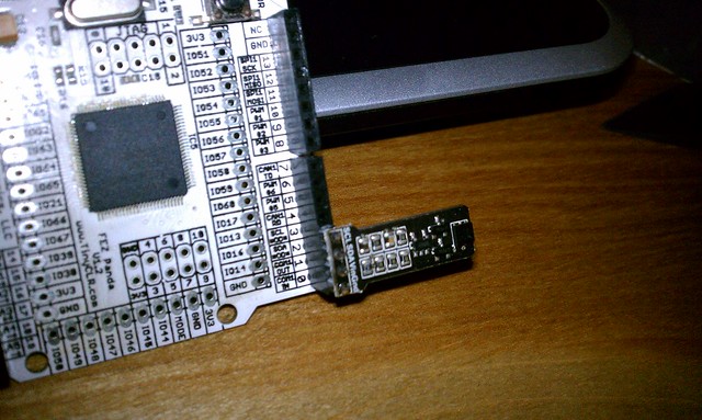
this is the way i ended up connecting it when i figured out the issue, youll see that the SDA and SLC pins are actually shift one over from where i thought they were supposed to be.
I am interfacing SHT21 temp/humidity sensor with CC430F6137 micro-controller. My controller send stop condition, start condition and address of the Slave but never gets Ack from the SHT21. I have also attached a screen shot of logic analyzer with this post.
Could anybody help me how I can fix this problem. How can I check that my sensor is working fine. I have change two sensor but every time I get the same result as shown below. Any kind of help would be appreciated.

 :o
:o