SC20260N ADC input pulled low when channel opened

Hi Gus,

This one is a bit of a puzzle.

While testing a new batch of meter boards, one board appeared to be working correctly in every other respect: display, buttons, LEDs, USB, analog inputs, etc. However, the battery level was being displayed as 6.6 V, instead of the actual 4.0 V.

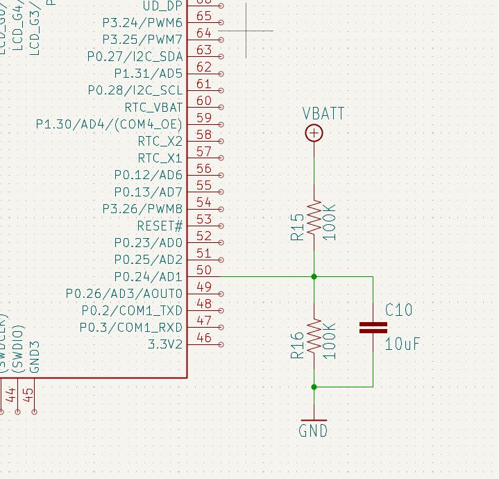
The battery is a single 18650 cell, currently sitting at about 4.0 V, feeding the ADC input through a divide-by-two resistor divider as shown.

Measuring the ADC input pin on the module showed 0.93 V, rather than the expected 2.0 V.

When stepping through the code after a restart, the voltage at the input is initially correct at 2.0 V, right up until the ADC channel was opened:


public const int VBatt = SC20260.Adc.Controller1.PC0;

var adc = AdcController.FromName(SC20260.Adc.Controller1.Id);
AdcChannel VBatt = adc.OpenChannel(IOMap.VBatt);

As soon as OpenChannel() is called, the input immediately drops to 0.93 V.

The displayed 6.6 V suggests the ADC reading itself is effectively full-scale, i.e. 3.3 V reference, which is then multiplied by two in the display software.

This is a brand new SC20260N module, pre-baked at 125°C for 24 hours, as I now do with all of them.

Any idea what could cause the ADC input to be pulled down when the channel is enabled, while the ADC reading appears to go full-scale?

That is extremely odd! I can’t see how enabling ADC changes the output. Even a manufacturing defect couldn’t cause this!

I wonder if this is the case on other analog pins.

Good point. We only use one other analog input, a 2.5V reference on AD5.

I’ll set up a test on it tomorrow.

1 Like

Using a minimal test app I found opening only the 2.5V reference channel doesn’t alter the actual voltage at either input, (Vref steady at 2.500V, VBatt at 2.0V), but the input reads full scale (3.3V).

Opening the Vbatt channel drops the actual input to 1.8V (rather than the 0.93V I was seeing yesterday with the full app), it still reads full scale.

Sorry I did not understand

You asked about the other analog pins. The board only has two connected as analog, my test showed that only the one on AD1 pulls its input low when opened, but both (AD1 and AD5) read full scale.

Board seems to function correctly except for this anomaly, thermal camera shows no hot-spots, current draw is normal.

Anything else I can check?

My understanding: 2 analog pins work as expected reading the full range when the pin is set to a specific voltage externally. But, one of the 2 pins seem to have a pull-down when it is enabled causing a 100K voltage divider to read the wrong value.

This should not happen!

Do you have working vs non working boards? Is it possible that these R15/R16 resistors are not the same values between working vs not working boards? I am guessing maybe the resistors are too high of a value, like 10M, causing the read to be off?

No, when powered up or reset (nothing enabled) there is 2.5V on AD5 (connected to a 2.5V reference chip) and 2.0V on AD1 (4.0V Vbatt across the 2 x 100k divider circuit.)

When AD5 is enabled, it reads 3.3V, its actual input is still 2.5V.

When AD1 is enabled, its actual input drops to 0.93V (when everything on the board is running) or 1.8V when only running a simple program that does nothing but enable the analog input.

The reading on AD1 is also 3.3V (full scale), except on the very first read when stepping through, it is around half of that, same for the AD5, I suspected a filter?

The resistors and capacitor are the correct value (measured).

We have several working boards in hand, over 100 running in the field.

I’ve been dialing in the pick & place machine, thought MAYBE it could have picked a wrong part, but everything looks good and I can’t think how any external part could cause those symptoms?

public const int VBatt = SC20260.Adc.Controller1.PC0;

var adc = AdcController.FromName(SC20260.Adc.Controller1.Id);
AdcChannel VBatt = adc.OpenChannel(IOMap.VBatt);

VBatt is declared twice as 2 different types.

Yes, just an extract from a larger context

    public static class IOMap
    {
        // Analog Inputs
        public const int VBatt = SC20260.Adc.Controller1.PC0;
        public const int VRef2p5 = SC20260.Adc.Controller3.PF9;
    }

where IOMap was a class that let us run the same code on EMX and G120 by dynamically switching the mapping.

Carried into the SC20 because we use the same source for that and the G120 .NetMF, with conditional compilation.

1 Like