I recently purchased a MotorCape mfg. by GHI and I cannot get this thing to make motors move. I have tried various software examples, e.g. some run and some have errors. Neither would make my two, separate motors turn.
Are other people using the MotorCape for the BBB? I have not found that it is very popular as of now. I realize it, this MotorCape version, just came out and it new.
…
I think the GPIO turns on the motor and then the PWM capabilities make the motor turn at a specified speed. I am not sure. I found on documentation on it yet. I have tried the character device GPIO interface and sysfs GPIO interface.
…
The overall look of the Cape is nice. I just cannot handle it right now. I have been testing w/ the MotorCape w/ a 12v 3.3Ah power supply while my BBBW is plugged in via USB.
I am running a BeagleBoard.org - latest-images image on the BBBW. If you would like other info. from me in regards to my set up and config, please let me know.
Seth
P.S. Oh and if you know how to use this Cape, please try to contact me. I erased the u-boot overlay that has to do w/ the Cape and I could not get it to work either w/ that method. Up the creek!
For motor control, you use PWM for the speed and Mx.HIGH to set the direction. There is no motor on/off control. Setting the PWM to off will do that. It can’t be any simpler than that.
How do you have this wired up to your supply and motors?
The geared DC motor is on MotorTwo and the leads from the power supply are as usual. That is all I am doing for now. I just wanted to get a geared motor moving for now. I removed the u-boot overlay for that specific Cape to make sure I could use available libraries in Python for it.
…
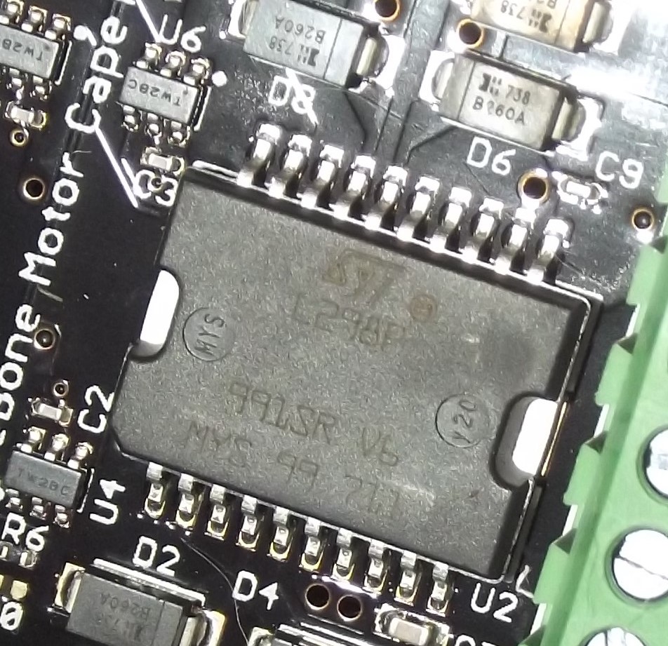
L298! I was unaware of this motor driver being on the Cape.
…
I actually made a L298 w/ two motors move before. This is good news. So, the GPIO just sets the LED on/off and the PWM sets the speed and off for the motor(s).
Seth
P.S. Thank you for this idea and info. on the subject. I was using the Adafruit_BBIO library to set up pwm signals via software. Is there another set of libraries you would use for Python?
I am not familiar with Python but surely you need a delay in the PWM so that it has time to run? You seem to STOP it, SET it and then STOP it with no delays between?
You need to set M2_HIGH to set the running direction. P9_14 is the PWM and P8_16 is the M2_HIGH control.
That is the chip, i.e. the L298p. Now, I am assuming that ST made it but the ST on the chip seems a bit ominous.
It is difficult to make out.
Anyway…
…
I have been unsuccessful w/ this chip on my MotorCape, esp. in relation to making a single, DC motor move.
…
I tried removing the u-boot overlay and reinstalling the overlay and I even added the u-boot overlay in my uEnv.txt file under the /boot directory.
I know you said you do not mess w/ Python. This is okay. I do not mind you not programming in Python.
…
I would like to mention something, though. The L298, in general, p or not, needs to have three pins dedicated to making it maneuver a DC motor. This is what I thought. If you have any ideas on this subject or making my MotorCape work as you know it can work, please reply.
If you are typing up C/C++ programs to run on the BBB w/ the MotorCape, please send a small snippet.
If you take a look at the Cape’s schematic you can see that you do not need three wires to connect a motor to it as the cape is doing all that for you - the HIGH signal is from your GPIO, the LOW is the inverse of that, and the PWM is what ENABLEs the driver to supply power. For the motor, you simply need the + and - wires. What I can’t find is what the relationship between the input voltage and the output voltage needs to be for a given motor rating - for example if there are 10v less presented to the motor than is presented at the input, then your 12v input will not suffice to run your motors - but the L298s are common so I don’t expect that to be a problem.
So lets go back to basics first.
Motors. What are their specs?
The motor power supply. You said it’s 12v and you say 3.3Ah, but that is a power over time measure, please provide better details about what supply it is and if it’s regulated or not. Have you measured the supply voltage when the cape is in use?
Can you please also measure if a voltage is present on your motor outputs when you do what you think the cape needs to drive it?
What address are you attempting to use to communicate to the cape eeprom - and I’m not sure how that’s meant to work (or what it does) but it’s on the schematic so it’s worth trying to confirm that the cape is responding to you, ie it’s not in some way broken. I assume this is really just to allow you to confirm in your code that yes, this is the cape you have fitted so you won’t destroy it.
Do the LEDs flash when you use PWM to drive the outputs? According to the schematic, they should flash at your PWM command…
Alternative approach here is to just set the PWM IO pins as high and confirm LEDs come on, as that again should be a fundamental behaviour that will show the cape is working.
I’ll also say that this is the Beaglebone.org cape, just so happens that GHI manufactured them, so there’s not a lot of discussion here on these devices (or BB in general). You may find other like-minded souls who have more experience than us elsewhere on the internet. But you will find us helpful, within the limits of what we know and can do.
I understand. I was using a 12v 3.3Ah battery supply for power. I will keep in mind that I can look elsewhere for support on this specific Cape from bbb.io persons.
Seth
P.S. Thank you for providing support thus far. I have gained some insight. Oh and the LED does not blink. It only turns on or off. I will keep trying. If you do not mind, I would like to post again once I have contained my situation on how to make my MotorCape function properly.
Don’t get me wrong, I’m not telling you to go elsewhere ! I just think that we might help get you to a solution, just not as fast as someone who has already used this device.
You are using a battery huh - well there’s a chance that’s your problem, depending on it’s power delivery capability. Is it new? Is it well maintained? Is it just a SLA battery, that’s possibly been sitting on a shelf for any time? Did you measure it’s output at all, when in use and when not?
Okay. I have not used this battery but it has not been maintained. It is a lead acid AGM 12v 3.3Ah battery. I just measured it via multimeter. I have not measured the volts while it is plugged in and moving electricity.
Seth
P.S. If you would like to have me test the battery or the MotorCape, BBBW, or all three, this is okay but you might want to give some guidance. I usually just wire up some items, I make sure the battery is fully charged, and I type up some software. Hit or miss at times but sometimes I figure out what the issues arising may be or have become.
ok great - SLAs or sealed Lead Acid battery, gel cells, are notorious for having a poor recovery from shelf life, as once the voltage gets below a certain point they are virtually impossible to drive to full charge. AGM = absorbent glass mat, a type of technology used in this kind of battery.
This means your battery may not provide sufficient power to run motors very well.
I think this is a valid test, but will let others also guide - I’d hook up the motor direct to the battery and confirm it works. I’d also though want to get a multimeter on it and confirm.
Ultimately, the best test of code is whether your LEDs light up correctly. With just using the PWM (Enable) signal as an IO, you should see the LED on. Set that up to cycle on and off every few seconds, and confirm it behaves right. Then change the on/off to be a 50% PWM signal, then what you should see is 50% LED brightness in the ON cycle, and completely off in the off cycle. Once you have that, move on to connecting the motor and battery, and again use your multimeter to confirm the voltage is showing on the pins as you would expect.
It is reading 12.18v on my AGM/12v 3.3Ah battery supply. I noticed you had typed that AGM batteries may not be suitable for motors. Which types of batteries would you recommend for messing around w/ motors, DC motors, and geared DC motors?
Seth
P.S. I will get back to you on if the software examples I currently use are making the motors run, e.g. this way I can test the motors while they run at the battery terminals. Oh and I will test for battery terminals to the leads of the motors w/out interruption soon. I will reply again w/ all this info.
If you can confirm that your code to toggle the GPIO is working and you can see the LED is on, then the only issue has to be either the battery power or your wiring. It’s just too simple otherwise for this not to work.
The brightness of the LED will change based on the PWM input frequency. Set 100% and it will be full brightness. At 50% PWM input, it should be dim by about half brightness.
12.11v is what registers when I apply the multimeter while the motor is wired up directly to the battery. I have some extra SLA batteries too. The AGM batteries are cheaper by far. I have a power supply, AC/DC, but the darn thing came w/ some shot instructions. I am going to take my time w/ it since I will be messing w/ 120v from the house.
Seth
P.S. My software is terrible. I cannot get the correct on/off and shimmer effect from the LED. I will keep trying.
Mr. Dave…Seth here. Okay, I know this should be easy b/c I have another module/device that uses the L298 in the other format. I have wired this thing up and used it many times but this Cape is giving me trouble most likely b/c I attempted to add the dt overlay w/out seeing that it was a dt overlay and not a u-boot overlay.
I am off to remove it. I will return service after I get the PWM set up and working for the LED.
I think you need to consider delays in your code after you enable the PWM output. You need some way to have the PWM run for, say 10 seconds, so that you can see it working. Your current test code, and I am no Python user, seems to just drop straight through without delays so I can’t see how this works.
import sleep and then add a
time.sleep (10);
after you enable the PWM. That will keep the PWM running for 10 seconds.
Seth here. Mr. Dave, I set up some “correct” software to run my motor from Motor1 and Motor2, i.e. each at separate times. For instance, I would run motor1 w/ the software and then test, after removing and replacing motor1 to motor2, motor2 w/ the exact same software.
I tried many software examples. I think my board is busted. I just ordered it.
I tested the battery, the motors, and the voltage when the motors are attached directly to the battery.
…
I received a “Do not reply for six hours” message yesterday. That is why I am replying so late today in place of yesterday.
…
If you need any more ideas from me, please let me know. I have contacted Mouser about the product.
Just for reference, my LEDs for Motor1 and Motor2 work. They blink on and off now. I can make them glow solid for any amount of time I choose, too. I can turn them off, also.
I still don’t think you have the software piece resolved that will allow us to say 100% that you have a busted board.
With PWM, you should be able to get different levels of brightness out of the LED. So you can change it from say full on to 7/8th after 10 seconds, then down to 3/4 bright, then down to 5/8ths, then half, etc, and clearly see that the state changes (ok as you get towards the lower part of the scale it will be harder to see!). You haven’t shown us any of your code now you understand things more, so perhaps it’s worth popping up a version of that so we can see.