PWM Glitch?

Duino with FW 2.1.0.60000

I use PWM to control the switching of a MOSFET for a boost converter, and also to manage the charge on a capacitor (via an optocoupler) to vary the output of a voltage regulator. To do this, I keep the pulse width at, say, 30uS, and vary the frequency (I always do it this way). There is also A/D feedback to sample the output voltage so it can be intelligently controlled by varying the frequency.

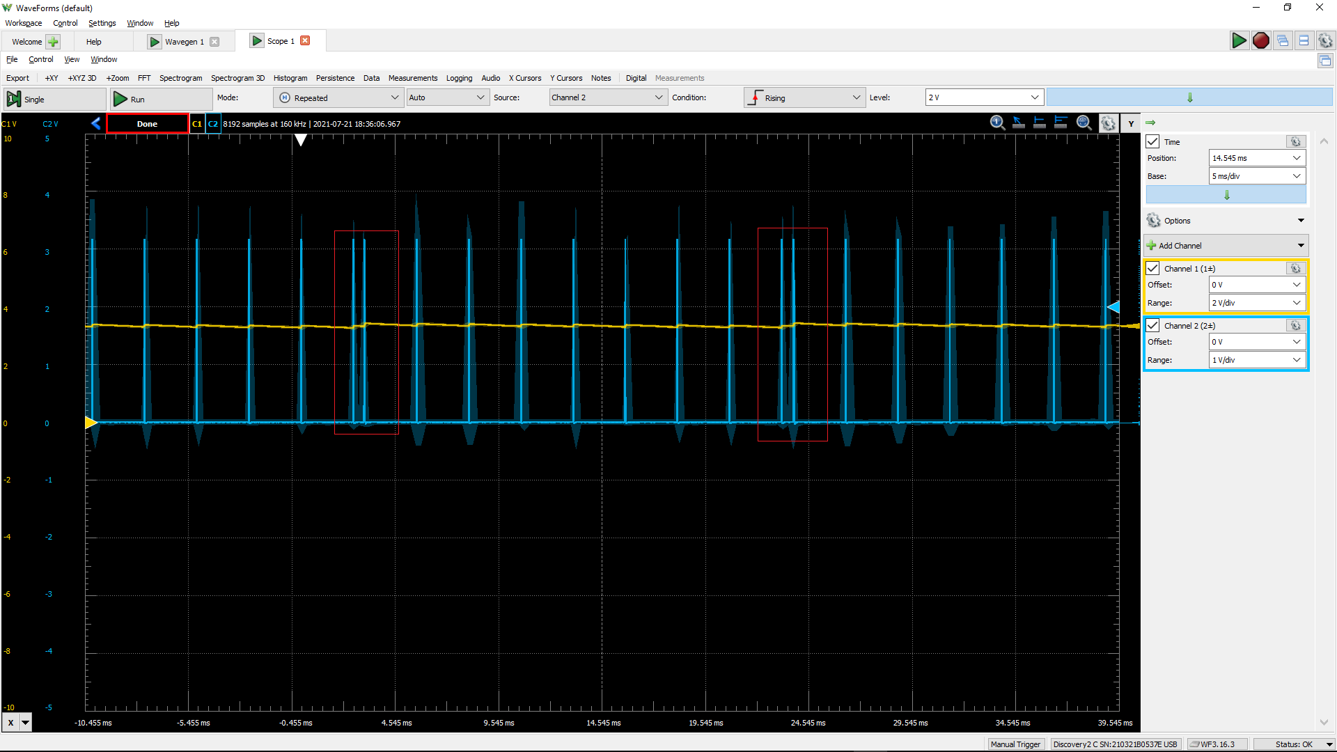
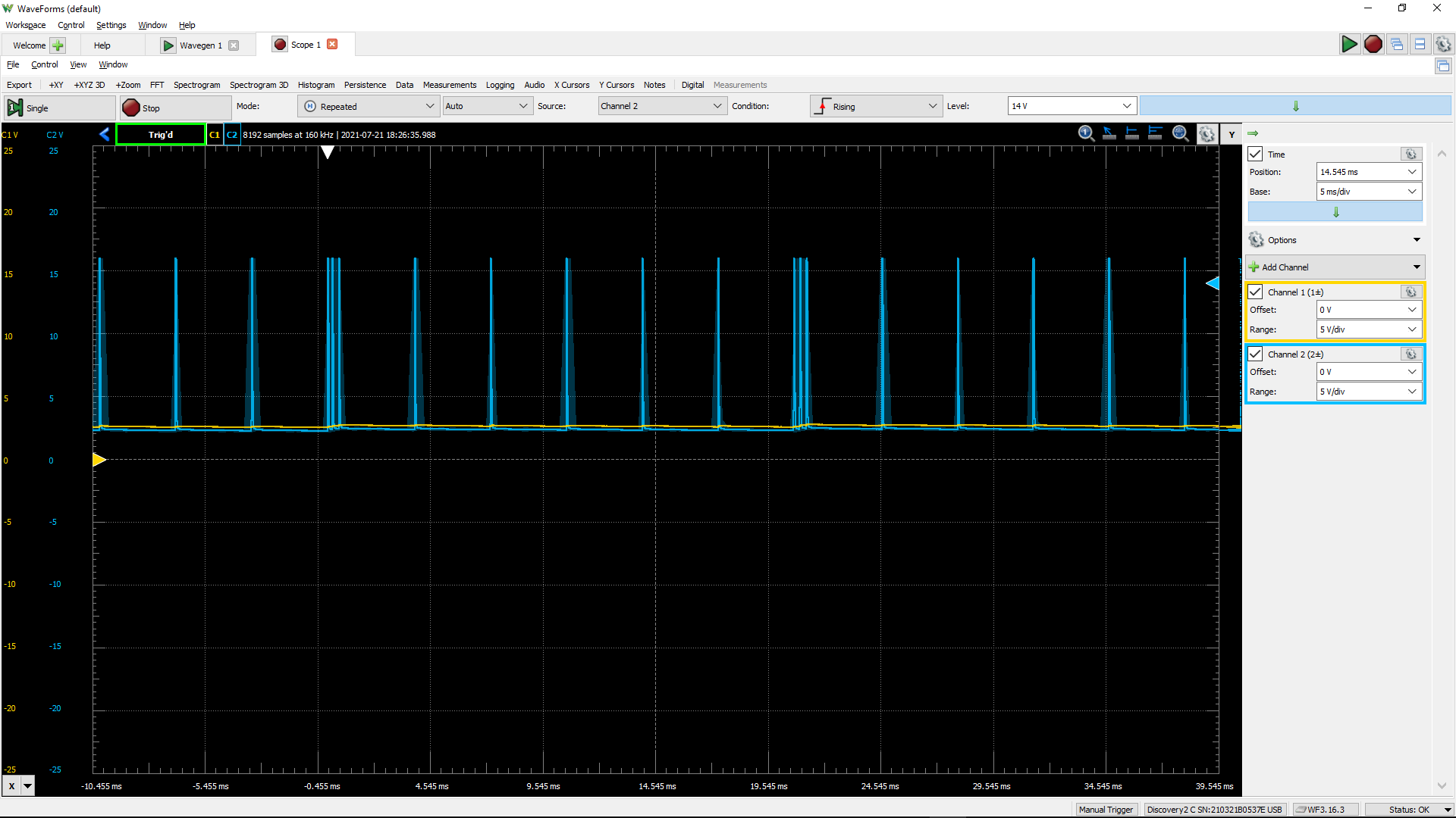
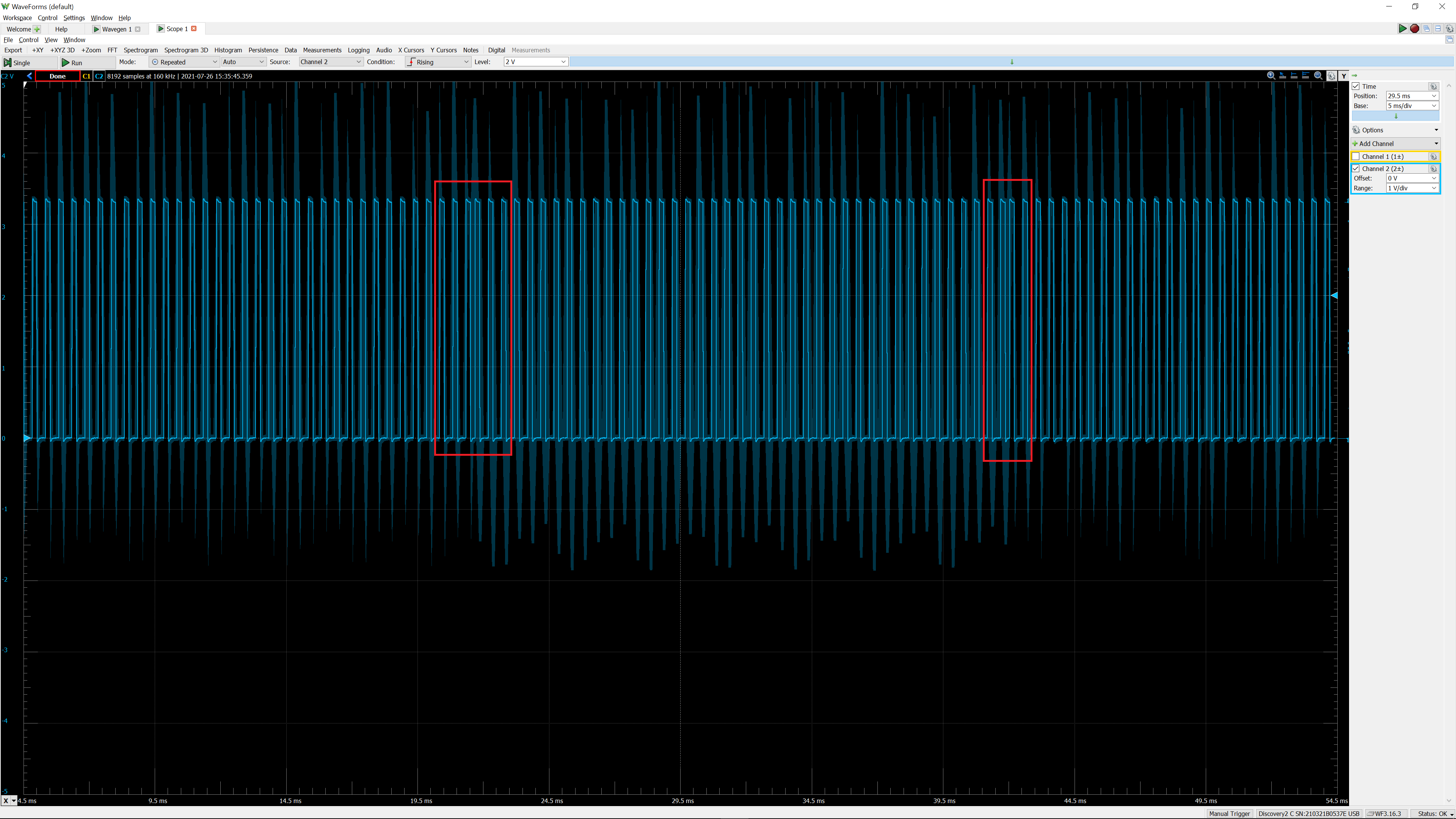
The problem is that when I set the frequency (controller.SetDesiredFrequency()), and also adjust the pulse width to keep it at 30uS (pwm.SetActiveDutyCyclePercentage()), the PWM outputs an additional pulse. This causes a noticeable jump in the voltage (see picture), and the voltage feedback value is inaccurate (unless I delay a while, which slows everything down).

Hereā€™s a scope shot which shows the problem.

Has anyone else noticed this? I could not find anything about it in the forums. I can do a workaround, but it would be far better to have a smooth transition.

Below this is the test code Iā€™m using. The Duino buttons control the frequency. (This is only test code, without the feedback. The final version will be rather more sophisticated.)

	static void pwmtest()
	{
		var gpio = GpioController.GetDefault();
		var appButton = gpio.OpenPin(SC20100.GpioPin.PB7);
		appButton.SetDriveMode(GpioPinDriveMode.InputPullUp);

		var ldrButton = gpio.OpenPin(SC20100.GpioPin.PE3);
		ldrButton.SetDriveMode(GpioPinDriveMode.InputPullUp);

		var controller = PwmController.FromName(SC20100.Timer.Pwm.Controller3.Id);
		var pwm = controller.OpenChannel(SC20100.Timer.Pwm.Controller3.PB0);

		// keep pulse width fixed and vary the frequency to control the voltage
		double step = 1;
		double freq = 1;
		double pulseWidth = 30e-6;		// 30 microseconds fixed pulse width
		double period = 1 / freq;
		double dutyCyclePercentage = pulseWidth / period;

		controller.SetDesiredFrequency(freq);
		pwm.SetActiveDutyCyclePercentage(dutyCyclePercentage);

		pwm.Start();

		double change = 1;

		while (true) {

			if (appButton.Read() == GpioPinValue.Low) {
				if (freq >= 80000)
					continue;
				change = step;
			}
			if (ldrButton.Read() == GpioPinValue.Low) {
				if (freq <= 0)
					continue;
				change = -step;
			}

			if (change != 0) {
				freq += change;
				change = 0;

				if (freq <= 0) {
					pwm.SetActiveDutyCyclePercentage(0);
				}
				else {
					// keep the pulse width the same for all frequencies
					period = 1 / freq;
					dutyCyclePercentage = pulseWidth / period;
					Debug.Assert(dutyCyclePercentage <= 1.0);

					controller.SetDesiredFrequency(freq);
					pwm.SetActiveDutyCyclePercentage(dutyCyclePercentage);

					Debug.WriteLine(freq.ToString());
				}
			}
			Thread.Sleep(20);
		}
	}

and sometimes there are two extra pulsesā€¦

Iā€™m just taking a wild stab at it here because I have not experimented with it, but this isnā€™t surprising to me. I suspect that changing the frequency means establishing new timer settings in the hardware timer registers. Either writing to those registers or re-starting the underlying hardware timer results in an immediate first pulse. That would explain one ā€˜extraā€™ pulse, though not two (unless other lines in your code also kick off a similar pwm timer restart).

Thereā€™s an underlying hardware timer, and it sounds like you are expecting the next pulse interval to be based on the new cadence rather than taking immediate effect. I believe that the change to the pwm registers controlling the base frequency takes immediate effect and essentially starts a new pulse train.

On the other hand, pulse width can change smoothly because you are just changing a duration that is started by the edge of the pulse. The base frequency isnā€™t changing - just the width of the pulse triggered at that frequency. Changing the timebase seems to restart the underlying timer.

Normally there are ā€œshadow registersā€ which take the new frequency and new duty cycle and only switch them in at the end of the current cycle. Then everything is smooth. There may be a configuration which enables this feature (e.g. PWMLER latch enable register).

I patched out the SetDesiredFrequency() call and call only SetActiveDutyCycle(), and I still see the double-pulse problem.

This could be nasty if you were, for example, controlling a stepper motor whose position depended on an accurate number of pulses, and whose speed was controlled by the frequency. But, as you say, maybe this does not work with frequency because of the timers in the controller.

Maybe it is worth checking it outā€¦ But (for my application) there is no hurry for this.

2 Likes

Very Interesting - With some deeper reading on my part, it does appear that the STM32 chips have support for smooth transitions too, via the UEV (update event) mechanism.

All of this is down in the firmware native code, but youā€™ve convinced me that this isnā€™t a necessary artifact of fiddling with the timers. Apologies that I canā€™t offer anything more useful - GHI will have to dig into this in the firmware code.

Yep, itā€™s all down to firmware native code, but we canā€™t mess with that (yet :wink: )ā€¦

Fixed in next release.