What about all the other pins? will you just leave them unconnected?
Basically all you can do with this now is push a button to turn on user led 
Yes yes, I hear you. This is just my attempt to get TinyClr on a tiny board and at the same time get into KiCad. Next step is to integrate this into a product. For this I need 2 things: HID support (Mouse/Touch) and a custom made sensor. The custom sensor I have.
You need a 0.1uF ceramic cap next to the VDD pin. I would also put a 4.7uF cap in parallel with this. You’d be surprise how many times lack of decoupling causes spurious resets.
Suggest too that you put some ESD protection on the USB lines and keep them parallel and as close to the same length as possible. I like the USBLC6-2SC6 as you can connect on one side and exit on the other. Makes insertion easy.
Make sure that when you do the PCB you use thick traces for power and ground connections. Try 40mil as a min but you can step down to connect to the processor pads. Other traces can be 8 or 10mil. The USB should really be differential with 90 ohms but if your connection is short, you will get away with this.
Lastly. Consider bringing out the UART and I2C pins to a header. That way you can do further testing.
Good luck.
1 Like
He @Dave_McLaughlin, thank you very much for your input and suggestions. I’m going to digest it all and see what you mean by it 
For now, I could not resist but to share this photo of my proto setup. It actually works … aint it magic?

Prototyping on 2.54mm is much easier then on 1.27mm. Perhaps I’d make a 2.54mm breakoutboard for the SCM20100E for proto purposes.
2 Likes
Now going through your suggestions 1 by 1 …
You need a 0.1uF ceramic cap next to the VDD pin. I would also put a 4.7uF cap in parallel with this. You’d be surprise how many times lack of decoupling causes spurious resets.
I sure don’t like surprise resets. Checking the SCM20100E schematic (*) ( sheet 1, block D1), I see this:
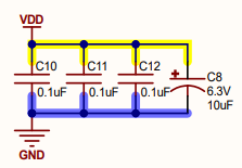
Would that provide sufficient protection against the spurious resets?
…some ESD protection on the USB lines and keep them parallel and as close to the same length as possible. I like the USBLC6-2SC6…
OK, never thought of that. Looks robust. I see in the datasheet that besides the wiring, the PCB layout is of importance here. I like this idea and will put it in. I’m not sure if I understand the schematic right, but I will give it a go.
Try 40mil as a min but you can step down to connect to the processor pads. Other traces can be 8 or 10mil.
Thank you for this suggestion … I will put it in the pcb layout and post the results here.
The UART and I2C pins
For my actual application I indeed need I2C and another GPIO. So that will be added.
The UART perhaps because I need it for debugging?
Again, many thanks for your suggestions …
(*) SCM20100E schematic: https://docs.ghielectronics.com/hardware/sitcore/pdfs/scm20100e-rev-b-schematic.pdf
Even if the SOM has these on board, I still prefer to use an external bypass at the module power pins. The small cost of a couple of caps for peace of mind is worth it. You can always leave them unpopulated and only add if you experience supply issues.
Many thanks for the feedback sofar. The schematic is getting more mature at every step. Here is the update thusfar:

I added:
- ESD protector (USBLC6-2)
- Ferrite bead (as per recommendation in silabs doc)
- 0.1uF and 4.7uF caps in the power section.
- Connectivity block: 3.3V, GND, I2C, 2 GPIO PINS and UART1 TX/RX.
Is this done right?
ps: In the EFM32 usb hardware design guidelines … on page 5 for “Bus powered USB device”, it states as one of the recommendations: ‘Use a ferrite bead for VBUS. Place near receptacle.’. Is that wise todo here as well, to reduce noise? I did not read anything about that in the STM32 guidelines.
When new components are in, I’ll update the prototype.
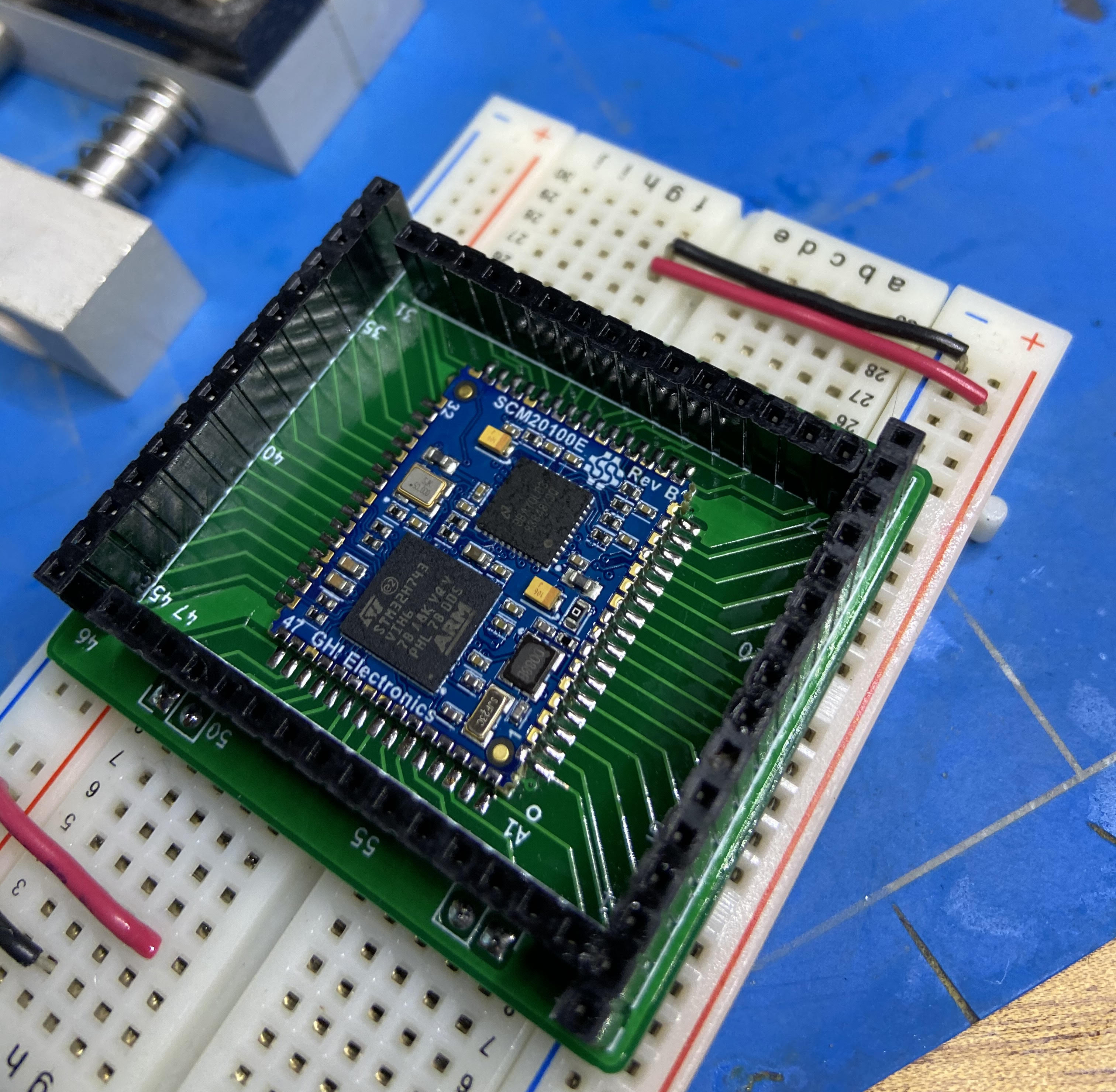
I followed up on the suggestion of @Dave_McLaughlin to have a board made. It’s not exactly a full-flex oven controller (YET), but it is a … break out board for the scm20100E. Hope it helps putting together prototypes quicker …
6 Likes
good job. a BoB is alwats a good thing to have. Just to humour me, you’re only sitting the thing on the breadboard aren’t you, it doesn’t have long tail pins that go into the breadboard?
Putting all 61 pins of the SCM20100E onto a breadboard (in two lines) would require 30 positions on the breadboard. That’s a lot of space. This layout makes all 61 pins available using less space. With jumpwires its easy to setup any prototype. Works for me.
cool, so just confirming, I was hoping you hadn’t put long pins that went into the power rails of the breadboard, and your comment implies not… cool.
I totally agree, the BoB model like this is great, half a dozen or so jumpers for what you need into either external modules or onto a breadboard to do discrete prototyping if needed is such a good way to work. USB is the only hassle, unless you have that sneakily hidden on the underside of that board (which BTW would be an awesome extra if you did have it added; possibly a barrel jack too for power in)
The objective indeed is to add the usb with power circuitry… will post updates and or requests for feedback …
2 Likes