I am doing a project which involves developing scripts to run on individual DUELink modules. I am using the builtin library functions and the driver functions.
The library functions reference PIN numbers. Those modules which have pins exposed externally are labeled P1..P12.
I have seen in a driver where there was a function to get a PIN number for an included button. The function just returns a number.
I found an Arduino sample which had a lookup array where the array index was p1..P12 and the array contents had PAx, PBx… the chip pin notations. Using the schematic I could then find the PIN number.
There are lots of clues, but I think like would be simpler if there was documentation on what PIN numbers to use with the library function for each board.
Questions…
I assume the required PIN numbers for the library functions are the CPU chip numbers?
Are P1..P12 always mapped to the same CPU chip pin?
All modules share the same core schematic, the same pins, the same functionality. Maybe I didn’t understand the need or the question. I am not sure why you are looking at Arduino code, unless you are planning on coding the modules using Arduino.
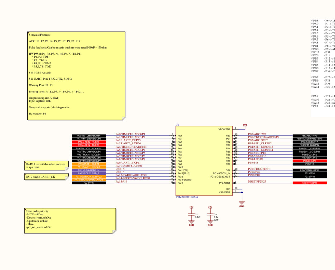
The page from the schematic is what I was trying to find.
With a bit of embarrassment I have to admit the print was too small for me to see when I first looked at the schematic. I had to blow it up to see that the information was there.
I will gather the info and post a table here within a day or two.
Some days, I find myself questioning everything I believe in.
I had assumed that the standard library used the PIN number on the CPU chip when referring to a pin.
Based on this assumption, I created a Px to CPU pin table using the schematic page provided.
However, when I tried to verify the table using the STAT led, which is connected to CPU PB8 pin 22, it didn’t work. I had released the LED from the engine.
I was puzzled and decided to try using zero as the PIN number, since I wanted to toggle P0. It worked!
After further verification, I now know that the PIN numbers required in standard library functions are the numerical portion of the Px designation. The LED pin is referenced as 0 in library functions. A P1 pin, exposed externally on a module, would be referenced as pin 1 in a library function.
It’s a simple and elegant system, but was not intuitive to me. I overcomplicated it.
Would it be appropriate to include a brief comment at the beginning of the standard library documentation to explain the pin numbering scheme?