You’ve got that swapped around. BOOT0 is H1, the pin with the square outline.
Oh ! 
Thanks to verify. So in order:
| GND | TX | RX | BOOT0 |
|---|
Yes. BOOT0, RX (input to host), TX (output from host), GND
1 Like
Another question: FEZ must be powered I suppose ?
Best to power it and keep it in reset or loader mode so it is not driving any of the WiFi pins.
2 Likes
I try to connect USB to serial (115200,8,N,1,N) as follow:
| FEZ | GND | TX | RX | BOOT0 |
|---|---|---|---|---|
| Usb to serial | GND | RX | TX | GND |
But when I try to send AT command: Nothing.
So I try
| FEZ | GND | TX | RX | BOOT0 |
|---|---|---|---|---|
| Usb to serial | GND | RX | TX | 3.3V |
But Nothing too !
I do a mistake, but Which ?
There is a RESET# line and this is driven by the CPU. This is pulled down and the CPU GPIO will be high impedance so chances are the reset line is still low and holding the device in RESET.
Secondly, GHI have GPIO9 pulled high so during boot the SPI interface is selected so that would explain why, even if you did sort out reset, the reason no response from the UART.
Handy datasheet for the WiFi module. ![]()
2 Likes
Thanks for this information. @John_Brochue has only told of H1 connector, so I was thinking that only this four pins connector was involved in wifi update.
It seems there is no connector to access RESET# and GPIO9 wifi pin.
As both the RESET# and GPIO9 are connected to the CPU, you could develop code to pull GPIOI9 LOW and then reset it. This should put the device into UART mode.
In fact, you could do the update this way by loading the data from the SD card.
@Dave_McLaughlin: good point !
I try with that code, but nothing happens.
using System;
using System.Diagnostics;
using System.Threading;
using GHIElectronics.TinyCLR.Devices.Gpio;
using GHIElectronics.TinyCLR.Pins;
// ReSharper disable FunctionNeverReturns

namespace testFEZWifiToUart
{
    internal static class Program
    {
        private static GpioPin _pinReset;
        private static GpioPin _pinUart;
        private static GpioPin _pinLed;
        private static GpioPin _pinButton;

        static void Main()
        {
            var ctl = GpioController.GetDefault();
            _pinButton = ctl.OpenPin(FEZ.GpioPin.Btn1);
            _pinButton.SetDriveMode(GpioPinDriveMode.InputPullUp);

            _pinReset = ctl.OpenPin(FEZ.GpioPin.WiFiReset);
            _pinReset.SetDriveMode(GpioPinDriveMode.Output);

            _pinUart = ctl.OpenPin(FEZ.GpioPin.A1);
            _pinUart.SetDriveMode(GpioPinDriveMode.Output);

            _pinLed = ctl.OpenPin(FEZ.GpioPin.Led1);
            _pinLed.SetDriveMode(GpioPinDriveMode.Output);
            _pinLed.Write(GpioPinValue.High);

            Thread.Sleep(2000);
            _pinLed.Write(GpioPinValue.Low);
            Thread.Sleep(2000);

            WaitForButton("Ready to reset Uart - Press a button...");
            ResetToUart();
            while (true)
            {
                _pinLed.Write(_pinLed.Read()==GpioPinValue.Low?GpioPinValue.High:GpioPinValue.Low);
                Thread.Sleep(100);
            }
        }

        private static void ResetToUart()
        {
            _pinUart.Write(GpioPinValue.Low);
            Thread.Sleep(5);
            _pinReset.Write(GpioPinValue.Low);
            Thread.Sleep(20); //Generous wait
            _pinReset.Write(GpioPinValue.High);
        }

        private static void WaitForButton(string msg = "")
        {
            if (!String.IsNullOrEmpty(msg))
                Debug.WriteLine(msg);
            while (_pinButton.Read() == GpioPinValue.High)
            {
                _pinLed.Write(_pinLed.Read() == GpioPinValue.High ? GpioPinValue.Low : GpioPinValue.High);
                Thread.Sleep(50);
            }

            while (_pinButton.Read() == GpioPinValue.Low)
                Thread.Sleep(50);
        }
    }
}
@valon_hoti_gmail_com: that is same info as in datasheet.
To access Uart, I set PA1 (GPIO9) as low and reset SPWF04S. It should be in Uart mode, should’nt it ?
I try to connect RX to TX of my USB Serial to confirm data send is receive, and it is ok.
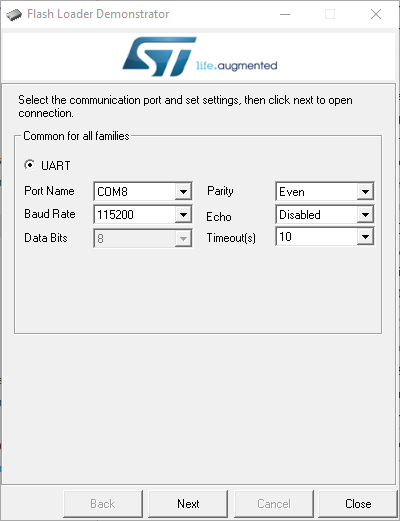
One other additional note is that when you do assert BOOT0, the Wi-Fi isn’t running its firmware anymore and is instead in DFU mode, so AT commands won’t work. You can use the Flash Loader Demonstrator from ST to communicate with the board bootloader and load the firmware that way. (You can’t use the usual DFU Tester tool since there is no USB)
1 Like
But UART Flash Loader has limit to 1 mb flash as i know this wifi have 2 Mb if i’m not right ??
I resume to hope to find error:
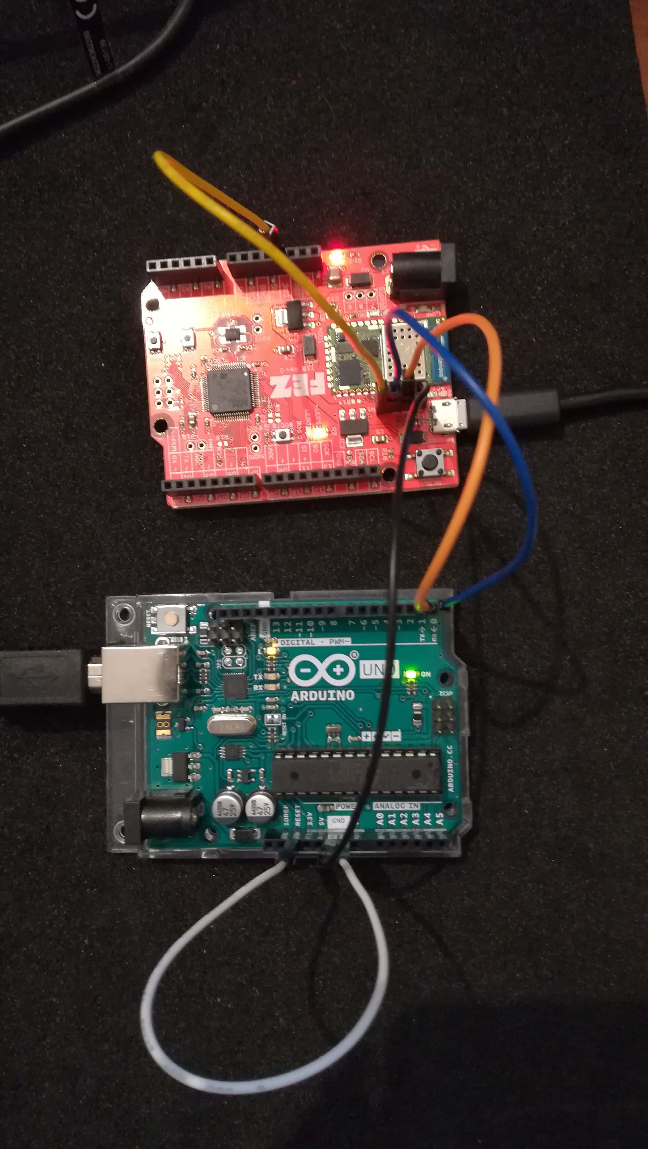
| Arduino | To | Wire color |
|---|---|---|
| RESET | GND | White |
| RX | TX (FEZ wifi) | Blue |
| TX | RX (FEZ wifi) | Orange |
| GND | GND (FEZ) | Black |
And
| FEZ | To | Wire color |
|---|---|---|
| WBOOT0 | 3.3V | Yellow |
| TX | RX (Arduino) | Blue |
| RX | TX (Arduino) | Orange |
| GND | GND (Arduino) | Black |
In my program, I set A1 (wifi GPIO 9) to low. Then reset wifi (Low/Sleep/High).
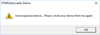
Although, even if Flash Loader Demonstrator see COM port, it can’t communicate with it:
I don’t know what I can look now !
If I don’t set WBOOT0 to 3.3V, shouldn’t I access normal UART communication with wifi ?
Did you try to swap rx and tx .? The Arduino RX TX labels are for the 328 and not the serial chip ? Connect rx to rx and tx to tx.
Yes I have already tried that. But all times:
Remove atmega328 from his bay
than use as uart only arduino board
No change ! 
Definity you need swd programmer (thete are some cheap about 3 usd to use it with st-link)