hello guys,
i have this simple pump that i’m trying to hack and replace it’s push button with an IR Proximity Sensor.
first let me explain how it works right now:
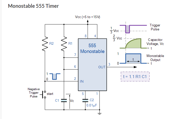
you press a button and it starts the pumping and last for 90 sec and shuts off (ic 555) is used for this purpose
while running you press the same button and it stops.
runs on 5v.
so what i’m trying to do is the following:
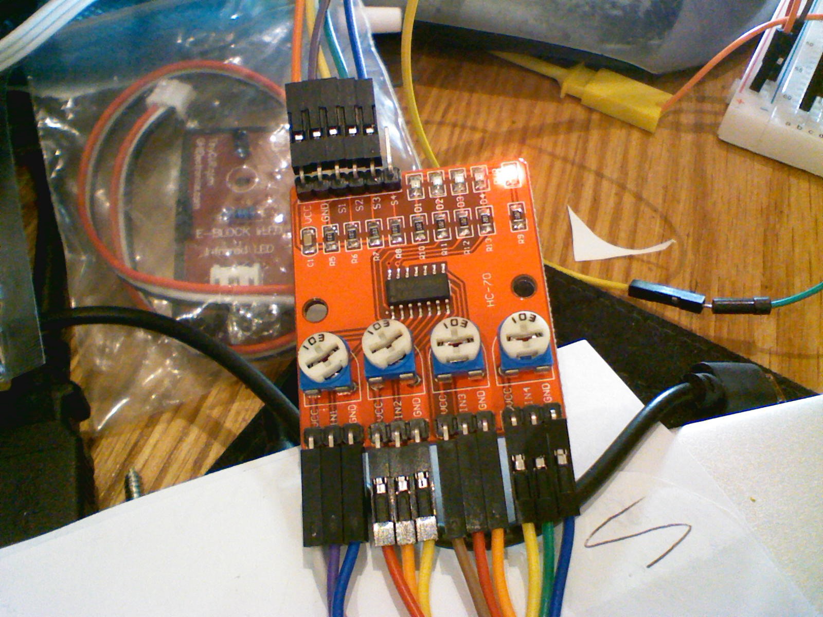
install an IR Proximity Sensor to start the pump while in proximity and stop the pump when my hand is away from the sensor.
limit the pump to 0.5sec min instead of a fixed 90 sec (for this i need to locate the fixed R and replace it with a potentiometer to allow the tweaking of time and replace the current cap with the right one to achieve a minimum of 0.5sec operation)
where am i right now:
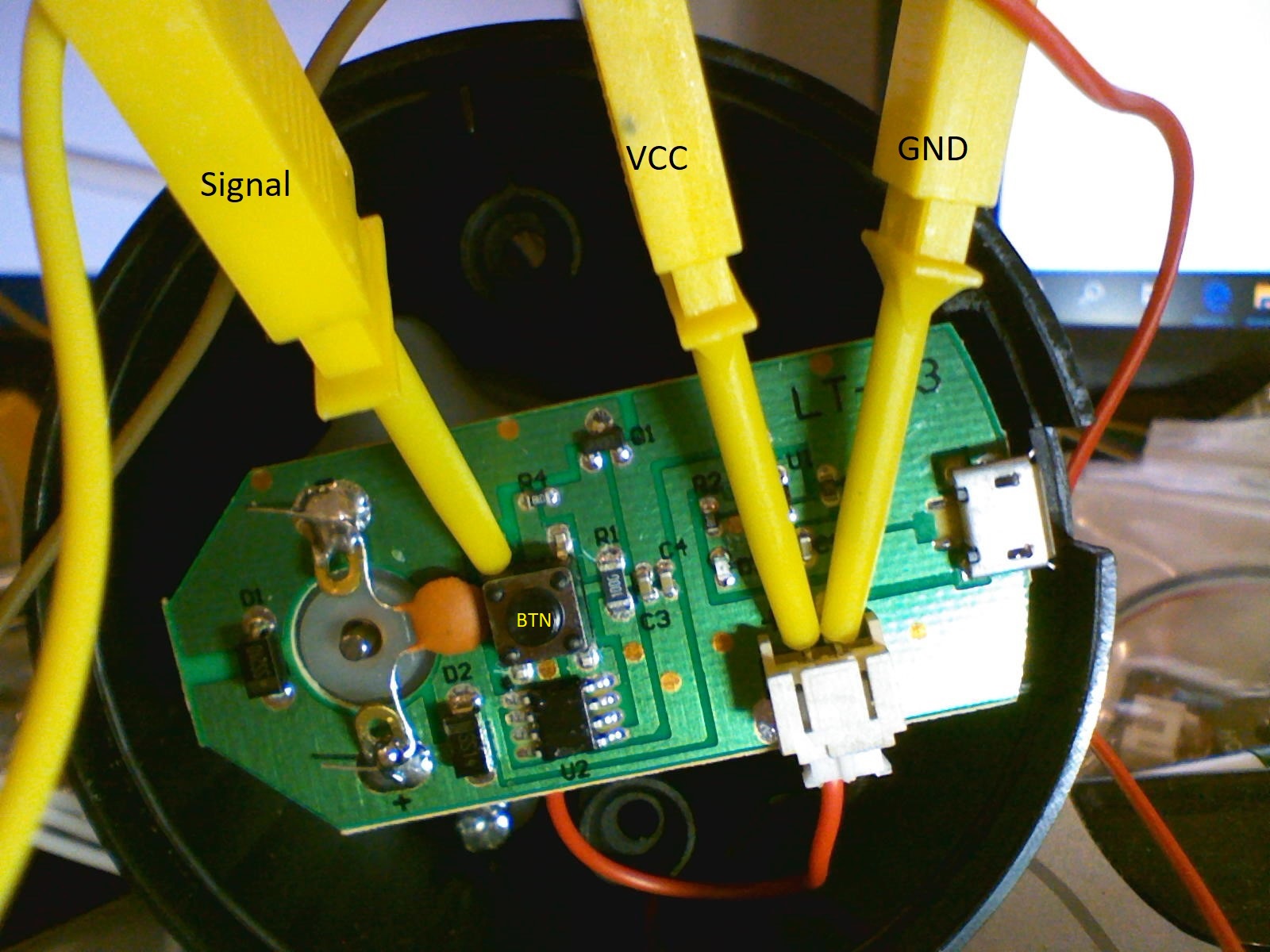
i have the IR Proximity Sensor powered by the same board VCC and GND.
i have attached the signal of the IR Sensor to one of the legs of the button.
when the sensor is activated the signal goes high and the pump works.
the problem:
the problem is the pump continues to work even if i remove my hand away from the sensor and only shuts off if i bring my hand in front of the sensor meaning the signal goes high again. not the desired outcome i’m looking for
can you guys please help me figure this out… remember i do not have any schematics and i want to achieve this as cheap as possible so no Micro-controllers involved here.
as for the timer:
i suspect that i will need to replace C3 and C4 or at least remove one to reduce the time, no???
also should the potentiometer would go in place of R1 ??
so it seems to me that the circuit in the black-box portion “latches” to turn on, and then the downstream 555 signal or second button press resets the latch. So you need to have your IR sensor behave like that, rather than behave like a switch as it does now. And if you think about it, the “momentary press” of the button is just a pulse, and then another pulse comes along when you press it to turn it off. That means logic patterns.
lol,
some progress, when i thought about it, i think what i need is actually just figuring it out how to limit the time from 90sec to 0.5 sec and it will solve my issue. as the proximity will start the pump and the timer will reset it.
so the next question anyone can point out if the capacitor to replace are what i highlighted please?
I’d say you need to check the circuit more to know how it’s working - the flip-flop / latch behaviour may mean it’s not a simple R or C change to change the delay
you have the package in front of you, a bit of reverse engineering wouldn’t go astray
Given the behaviour we’ve gathered from the push button on/off circuit, I’d assume that the output is not a monostable with time t like you showed. It’s more like a delay circuit - wait 90 seconds, then just output a single pulse. But again, reverse engineer the circuit a bit, in particular how the switch and the 555 output turns on and off the pump.