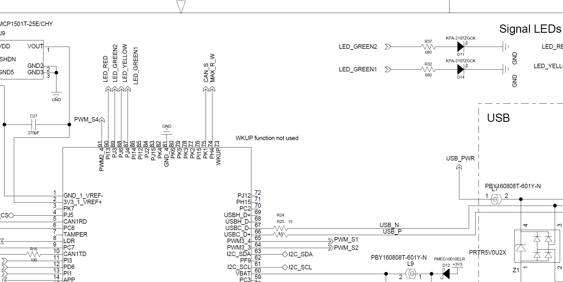
I am currently testing SCM20260N on a PCB. I have four LED’s on the PCB, but I am now starting to think I cannot use any GPIO pin to drive an output high?
I have tried the LED example:
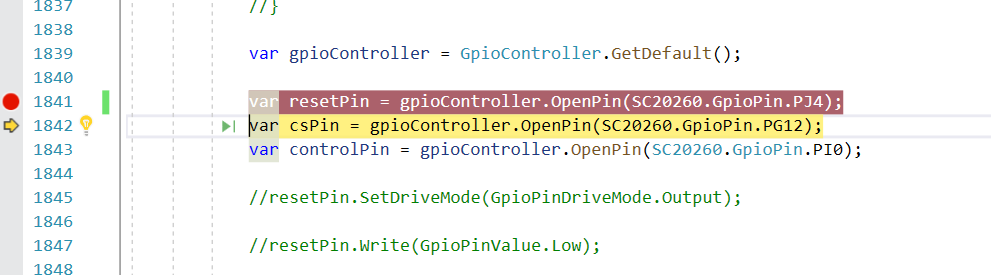
var led = GpioController.GetDefault().OpenPin(SC20260.GpioPin.PJ4);
led.SetDriveMode(GpioPinDriveMode.Output);

while (true) {
    led.Write(GpioPinValue.High);
    Thread.Sleep(100);

    led.Write(GpioPinValue.Low);
    Thread.Sleep(100);
}
But starting to wonder if only PWM pins will works since the debugger gives me an exception error:
Exception thrown: ‘System.InvalidOperationException’ in GHIElectronics.TinyCLR.Devices.Gpio.dll
An unhandled exception of type ‘System.InvalidOperationException’ occurred in GHIElectronics.TinyCLR.Devices.Gpio.dll
If I use a PWM pin there are no errors, but I don’t need PWM, I just want to drive it high. Are the LCD pins not general purpose (since I am not using an LCD)? It is not really clear which pins are general purpose or mandatory/fixed for a specific purpose from the colors in pinout picture.
Or, I could not find it at least… is it mandatory to use PWM pins for LED’s even when I only want to drive max. current?
No, I don’t use the pin somewhere else.
No, I do not set PWM on same pin.
According to pinout of SCM20260, PWM is not assigned for PJ4.
I don’t need PWM.
If I try to drive PJ4 high, it gives me an exception error. If I use a “PWM” pin (for instance PK1), “led.Write(GpioPinValue.High);” it does NOT give an exception error.
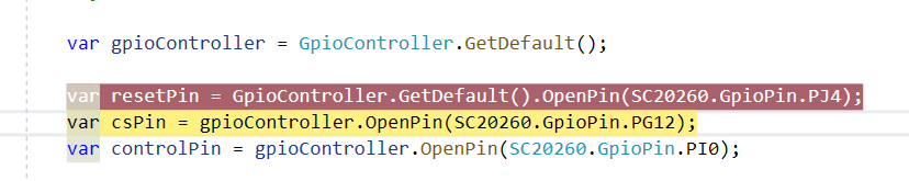
Hi, I declared it like you did (with separate gpioController declaration) and now it works! I am migrating from TinyCLR 1.0 and I declared as the example from the tutorial, it does not work:
        //Green indicator
        var greenLED1 = GpioController.GetDefault().OpenPin(SC20260.GpioPin.PJ4);