I have checked schematics from multiple companies and they all share the same lipo charging circuit, which I think it is wrong! Can someone tell me how I am wrong here please!
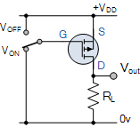
Here is how a P-MOSFET should work
It is used in lipo circuits, I am guessing, to power up the system from battery when there is no USB power. so lipo (VBAT) to system (VSYS) but this is backwards here
What I think, it worked because the internal protection diode that is built inside the transistor allowed the VBAT to flow into the system but this is not what the FET suppose to do!
Please tell me I am crazy here and not the entire world is copy pasting wrong design.
If they are using the diode to allow the battery voltage to pass through then surely 2 things to consider. 1, what is the current capacity in this state and 2, what is there to stop the diode conducting in when the USB power is active? The battery voltage will be lower than the USB voltage but surely some current will still be flowing to the output.
I need to set this up in Altium and do a simulation as it does seem a rather strange way to do this.