The only available tutorial code I’ve found so far comes with the disappointing caveat: “The sample code is meant for the FEZ Portal with it’s built in WiFi module.”
I’m running a FEZ Duino that also comes with a built-in WiFi module. I did manage to find an obscure code listing (I’ve since lost the link I’m afraid) that had some much improved hardware initialization that starts out with:
            const int RESET = FEZBit.GpioPin.WiFiReset;
            const int SPI_CS = FEZBit.GpioPin.WiFiChipselect;
            const int SPI_INT = FEZBit.GpioPin.WiFiInterrupt;
            const int ENABLE = FEZBit.GpioPin.WiFiEnable;
With some hacking, I was able to get the green LED to light next to the WiFi SOC to illuminate (it now blinks slowly) and also was able to get the Winc15x0Interface class to yield some info with:
            string[] ssids = Winc15x0Interface.Scan();
            int rssi = Winc15x0Interface.GetRssi();
            var MAC = Winc15x0Interface.GetMacAddress();
            var fwVer = Winc15x0Interface.GetFirmwareVersion();
Trouble is, after it appears that things are working, performing an Enable() doesn’t get the setup connected.
Does anyone have a working WiFi setup? Is there any example code anywhere other than the board-specific code in the Tutorial (that gets nowhere near working on the FEZ Duino.)
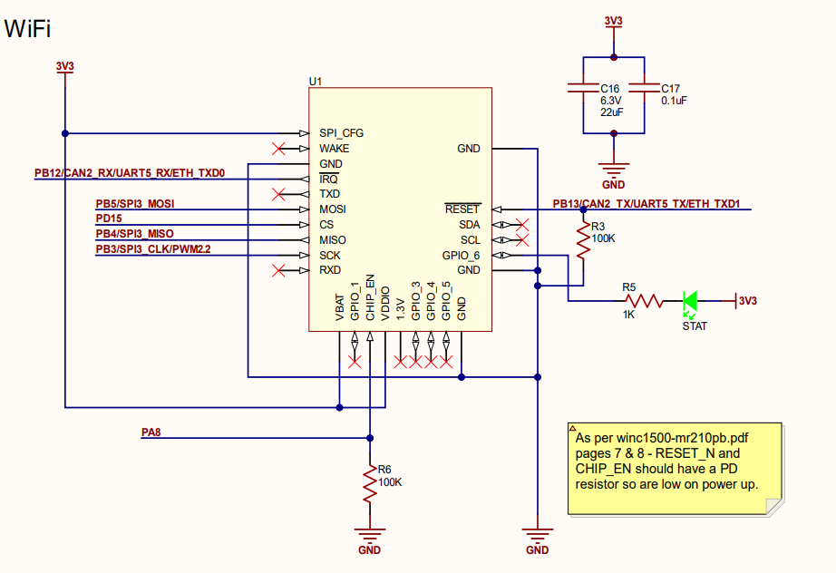
Hi, I am using both FEZ Portal and FEZ Duino with the sample code. The FEZ Duino is based on the SC20100 module, so you will have to change some pins and names to match that. The FEZ Duino WiFi parameters are written on the PCB:
ResetPin = SC20100.GpioPin.PB13
CsPin = SC20100.GpioPin.PD15
IntPin = SC20100.GpioPin.PB12
EnablePin = SC20100.GpioPin.PA8
SpiApiName = SC20100.SpiBus.Spi3
That should be all you have to change to make the sample code work.
I went through and made the necessary pin assignments and was able to get the device to flag a ‘connected’ state for a few runs.
But I noticed that the debugger would become unresponsive through Visual Studio and had to END-TASK Visual Studio a couple times.
Now after that, the debugger would not connect and the device will not connect even through the TinyCLR config tool, which is somewhat disappointing as it indicates a level of fragility that at least for my purposes is unacceptable.
After several troubleshooting steps, it was discovered that if I press & hold the APP button down while the TinyCLR Config tool attempted to connect that I could get the tool to connect. I had to erase both the Firmware and Application (reloaded Firmware) to get the board back to a state where code could be deployed to the device.
Caveat programmator
Just be aware that the VS2022 debugging session goes unresponsive when you attempt to single-step through the WiFi code after it’s connected. Especially the event handlers for connection state. There’s something about the WiFi module that doesn’t play nice with the VS debugger / plugin. None of my other classes or example code modules have this particular problem at all, it only manifests when working with the WiFi module.
This is what happen when your program gets into a tight look upon startup. The debugger cannot attach to the running process because the CPU is too busy. That is why the APP button was added. TinyClr checks the App button before launching the user program. If the button is pressed, then the user program is not launched.
If your code contains any tight loops, such as checking for a state change, add a short Sleep() to allow the debugger to attach.
Thanks for the note, but that is why I tried that avenue. Thing is, there’s no tight code loops in that code, but I did find out that if you take a look at the specs of the WiFi SOC and read that the clock frequency is 40Mhz, and if you put that value in the ClockFrequency = 4000000, property (instead of the 4Mhz value as shown) it really doesn’t like it.
So, no idea why we’re putting 1/10th the actual clock frequency in the property setting here (but that IS what you must do) - UARTs typically have divided values of the main clock, but because there’s no docs on the classes/ methods I couldn’t be sure if they’re looking for the main clock speed or the divided clock, ha. (Hey GHI…please put XML docs on your classes and methods. )
Thanks for taking a minute to reply. And of course the quandary here without docs is simply not knowing if that value is a typo or meant to be, as you have explained. All good though, my code is working and I was able to get my board to sync with an NTP server last night so we are trucking on.
Just a note though, ha. If the WiFi MCU is anywhere from 10-20cm away, then even a 4Mhz clock square-wave would probably look more like a jittery sine-wave by the time it reached the CPU, ha.
Lack of documentation is a serious issue. The “tutorials” are not tutorials. They’re mostly just a listing of calls with a note or two and crucial information stashed away in separate locations. There are zero comments about what the functions do in the actual library and there’s no documentation elsewhere. You can only assume what the functions do.