Can someone help me out with I2C,
I want to link a few of G30TH modules with I2C and have 1 master light a LED on each of the slaves.
How do I get/set an I2C address of each of the devices?
How do I send some command to particular device?
How do I read the command on a slave to light a LED?
The documentation about I2C is pretty poor.
This is what I got so far:
 class Program
    {
        static int delay = 100;

        static GpioPin led = GpioController.GetDefault().OpenPin(G30.GpioPin.PC8);

        static I2cDevice slave1 = I2cDevice.FromId(G30.I2cBus.I2c1, new I2cConnectionSettings(0x1C));
        static I2cDevice slave2 = I2cDevice.FromId(G30.I2cBus.I2c1, new I2cConnectionSettings(0x1C));
        static I2cDevice slave3 = I2cDevice.FromId(G30.I2cBus.I2c1, new I2cConnectionSettings(0x1C));
        static I2cDevice slave4 = I2cDevice.FromId(G30.I2cBus.I2c1, new I2cConnectionSettings(0x1C));

        static void Main()
        {
            led.SetDriveMode(GpioPinDriveMode.Output);

            while (true) {
                LightLed();
                LightSlave(slave1);
                LightSlave(slave2);
                LightSlave(slave3);
                LightSlave(slave4);
            }

        }

        static void LightLed() {
            led.Write(GpioPinValue.High);
            Thread.Sleep(delay);
            led.Write(GpioPinValue.Low);
        }

        static void LightSlave(I2cDevice device) {
            device.Write(new byte[] { 1 });
            Thread.Sleep(delay);
            device.Write(new byte[] { 0 });
        }

    }
its unusual to want to be an I2C slave device, usually the micro will be the master. If I recall, there is no netmf i2c slave code, and I can’t say I’d imagine that changing, so you’re likely going to need a different connection method
Ok, so if I use one G30 to be the master, what can I use as a slave to control a LED?
I need to use maximum of 4 wires, so I though VCC, GND, SDA, SCL to connect 4 of them together.
Also wouldn’t I have to ‘pass on’ messages with UART?
Lastly I already use the COM1 port for something else, and COM2 pins I use for PWM.
What I left exposed are SPI and I2C
GND means you know that any device is operating at the same reference as the other - this can cause issues if you do not share them between two separately powered devices. But since you’re now saying you’re going to be powering them from a common power supply, you will of course need VCC.
Your challenge is absolutely in trying to achieve something that is workable. A set of G30/G80 with no available COM ports won’t work. A set of G30’s and trying to use I2C also won’t work. My suggestion would be to look for LED control chips that are I2C or SPI referenceable, like TLC59108 or PCA9685. But without knowing what you are trying to achieve, and what other constraints you might have, we’re all shooting in the dark
Ok, I though about it, and it got a lot more complicated that I first though. its no problem to create a new board with only what I need and exposed COM.
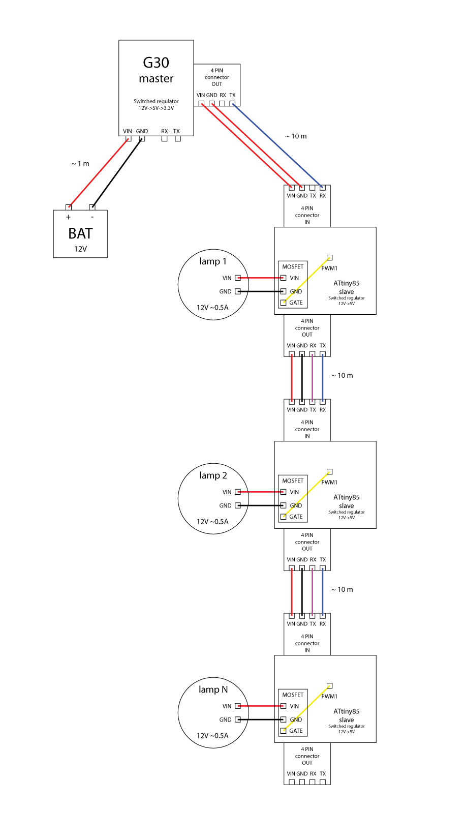
So I’ve created a sketch to illustrate.
This is sort of like a daisy chained LED chaser. Id like to use the G30 for the master and something very cheap for the slaves.
I was thinking of using ATtiny85, but if I can avoid regulating the power from 12V to 5V that would be better. I need something that can drive the 0.5A 12V lamp. Master will control it like a chaser 12345, 12345, 12345 or how every many lamps I connect.
Now I don’t know if I should use UART or I2C or SPI. I need to know somehow how many lamps are connected so I can set timings accordingly.
Is the traffic flow only from the master to the slaves? If so, then a serial input from each of the slaves could be connect to the serial transmit of the master, and a simple protocol implemented.
It doesn’t seem like you need a microcontroller at each LED. @Mike’s suggestion to just bit bang a GPIO pin seems pretty straightforward. You may or may not need a line driver for the 10 meters though. If you’re stuck on I2C, you could use an I2C to parallel IC. They are slave devices and you can set their address with jumpers and Digikey has lots in stock. As others have mentioned, the 10 meter distance is probably a problem. I2C isn’t really designed to drive cables and can only drive a maximum of something like a 400 pF load including the cable (if I remember correctly). If you don’t need the slaves to talk back to the master you can use RS422 or RS485 drivers for the I2C SCL and SDA lines. However, both those protocols use 2 wires per signal so that’s 4 wires total. If you stick with the 100 kHz I2C signalling rate, you can probably use RS232 which is still 1 wire per signal but it is kind of iffy for 10 meters…
What your turnaround delays with this library. It doesn’t work too well with fast replying devices. If you have control of the TX of each device on the bus, then you can optimise this for the library.
Second that. RS485 with a simple protocol. Modbus is overly complex for what you want to do. Roll your own in a matter of a few hours. Low memory on the ATTiny85 would benefit from a simple protocol. You will need some way to set the address for each one unless you do this via code with a fixed value. Not recommended.
Forget the 10m cable length, it probably will never come to that. It may be just 1m. This is just an illustration.
Forget the 4pin cables I can buy different.
My problems are I don’t know what to use.
The slaves are all the same, so the last one cant be different and cant have a wire that loops back to the master. They cant have a unique ID, cant be ordered, and cant be programmed differently.
So I need to know how many slaves are potentially connected to each other. It can be 2 or 10.
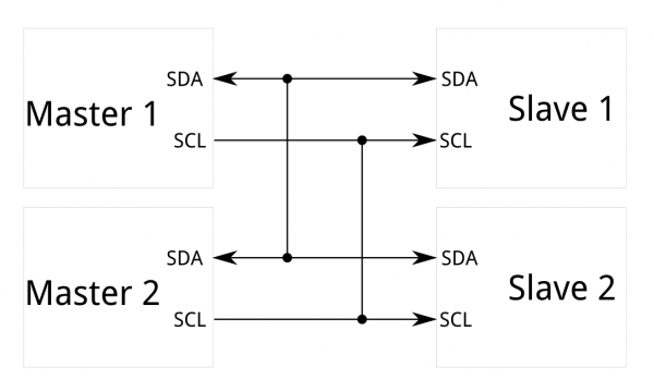
That’s why I2C seemed reasonable, I can set each slave to the same address, connect them like so:
and when they reply just count the number of replies and I have a number.
Now I just need to know the order of them.
Is this doable? will they all reply? or do they need to have different addresses?
Yes, Modbus is only suitable for not time critical applications. I just measured in an example I had actually set up that it needs about 300 MS to read a 16 bit register from the slave using a baudrate of 9600. That’s slow but on the other hand you can be sure that (unless your system is purposely corrupted) the command arrived at the addressed slave and that the received data didn’t get corrupted on the transport.
so many thanks for all the information that i have found here! you have no idea how helpful this example was for me and all he following posts! thanks a lot. i was just wondering if i may ask you people some questions? as i can see that you know these things much better than I do and plus, i’m new on the forum! thanks a lot!
Yes, if you are using the code in Codeshare, it suffers from poor turnaround delays. If you use this all with your own modules it works fine. I fell foul of the turnaround when I tried to use a Schneider VSD on the same bus. I was getting lots of errors and tracked it down to the fact that the VSD turnaround was way faster than the code I was using with NETMF. I changed the design to use an Atmel ATMEGA128 and now I can run them all on the same bus at 19200 and no errors. The ATMEGA code obviously runs much faster so can handle the turnaround times.
In a word, NO. Each I2C device must have a unique address or you will get bus arbitration issues. Same with RS485, CAN BUS etc. In fact, any bus based system where you have some form of multi-drop, each device has to have a unique address.