HVAC Conversion Project - Stepper Motors

Ok this is going to be off topic (but not quite so off topic since I’m using GHI stuffs.)

This beast…

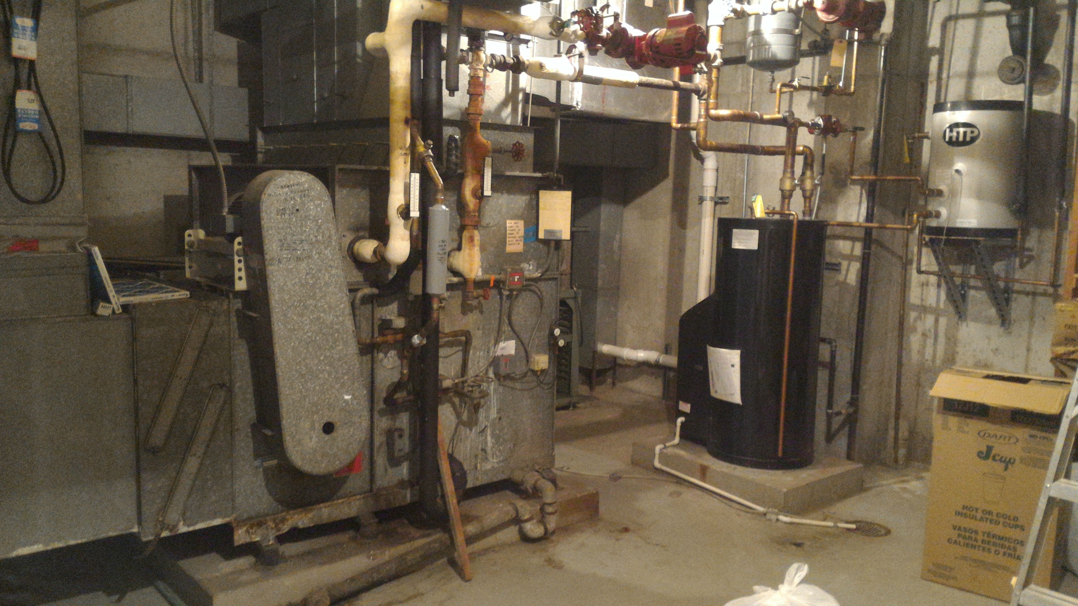
Is a 1970’s era Johnson continuous air dual plane HVAC system with an economizer.

It is pneumatically controlled - thermostats, relays, sensors, dampers… .they are all controlled by air pressure. That pneumatic system is failing. There’s leaks all through the building in air lines. Thermostats which are 40+ years old and not in the best of shape. Old air lines oozing air here and there (some in the walls, I think). The 40 year old compressor was running near continuously before it finally failed a couple weeks ago.

My very first embedded project isn’t going to be a robot, or a little gadget. It’s going to be an HVAC controller to convert this old dinosaur from pneumatic to digital.

I own the building, and my software company is based here, so it makes a good guinea pig. It’s an old bank building I bought a couple years ago. Sturdy.

The dampers… I was going to convert those from pneumatically operated to controlled via stepper motor. I don’t want to convert the dampers themselves; they’re just fine, and we’re keeping zones the way they are. They move easily; less than a pound of pressure will rotate them. Here’s a pic of the damper actuator side.

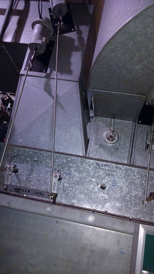
I want to control the dampers with stepper motors, controlled by the microcontroller. I’ve never worked with stepper motors before. Have NO idea what I’m getting in to there (but willing to drown myself in datasheets learning). Just need a starting point. The idea is to mount a gear to the stepper motor shaft, which will move the rod attached to the damper shaft, to open or close.

The other components;

I’m using a linear ADC2495 for my thermostat control and temp readings of hot & cold planes, hot gas bypass, boiler temp monitoring, etc. I just finished writing the driver for it.

I’m using an MCP23017 for GPIO relay controller and interrupt handling. Also wrote a driver for that (a complete one, as NONE of the libraries I’ve found out in the wild were feature-complete, and most were written incorrectly; mine handles interrupts, interleaved banking mode, etc.)

The idea is for those modules to be stackable for zone expansion, in case I run across another “paid” project in the future, I can add in up to 8 GPIO controllers for 128 additional GPIO ports and up to 27 Linear modules for 432 single edge analog inputs or 1/2 that in differential inputs. The idea there is to have purpose built control modules for zone expansion, etc, that I can stack on to the base system.

Anyways… back to those stepper motors.

For an application like this what should I look at? I’ve seen purpose built damper motors but they are $$$ and many require dampers to be swapped out. I don’t want to go through the hassle / expense of rebuilding the top of that big beast. I’d rather re-use all of the existing physical infrastructure than I can.

1 Like

It’s a little hard to tell exactly what you have to actuate. Can you mark up the photo showing exactlly what rod you have to move and about how far? Assuming you have to move the rod in a straight line, that means you have to convert the rotary motion of the motor to linear motion. Here’s one approach that is pretty straight forward:

http://www.robotshop.com/en/threaded-shaft-stepper-motor-29-oz-in.html?gclid=CjwKCAjw5PDLBRB0EiwAh-27MlFNqhz0klqvTbBLSs4I4ICw9bb0H0nELuWWP-YKLUYRsTwWNhtyHRoCNysQAvD_BwE

You may need a bigger or smaller actuator depending on how much force is required to move the rod. If it was me, I’d pick a motor that could generate at least 2X the required force, maybe 3X. You also need to make sure the actuator won’t move when it is powered off i.e., once you’ve put the damper where you want it and power it off, you don’t want the actuator slipping.

You will need to find an appropriate stepper motor driver. There are dozens out there.

I’m not a big fan of stepper motors for a lot of reasons, but they might work fine in this application. However, I would definitely add 2 limit switches somewhere on the actuator to provide a “damper open” and a “damper closed” signal. If you do that you don’t have to worry about the stepper controller losing counts and your actuator being in a position that isn’t what you think it is. You just run the stepper in the direction you want until the apppropriate limit switch fires and then turn off the motor. If you need to position the damper somewhere between full open and full closed, the limit switches just act as reference points and you run the stepper however many counts you need relative to one switch or the other. You should be able to find appropriate limit switches at McMaster-Carr or Digikey. This approach would also allow you to use non-stepper motor actuators which are smaller, more effiicient and usually quieter than steppers. You might also be able to find a DC motor actuator just like the one above that doesn’t need a controller. Just a relay that swtiches 12 or 24 VDC on and off to the actuator motor.

Most of my project have reliability as a much higher priority than cost. Depending on how many dampers you need to control, I’d go for motors and controllers from reputable companies. The example I gave from RobotShop may or may not be high enough reliabilty for a HVAC system that really need to work 24/7 for 10 to 20 years. If you google around you should be able to find a range of actuators from different vendors. I’d guess a good actuator of the kind I mentioned should be in the $50 to $100 and controllers should be in that same price range.

This looks like a fun hardware/software project!

I do not have much experience with stepper motors. If I get that right, you want to use them in order to open/close something like a valve? What I learned from my project (a flip flap train departure display) is that even though stepper motors provide a fine level of control due to the steps having a small rotation angle, it needs some kind of feedback/sensor in order to get reliable. Its easy to get stuck, I think even more in your case as you will probably have varying air pressure and therefore varying force needed to open/close the valves.

In my project I only needed the motor to either turn with a certain speed or stop. I used a single GPIO pin/signal for this with the idea that the motor turns one step when the the signal is pulsed. I realized this with a dual flip flop (CD4013BE, reused from the original PCB driving the stepper motor) for generating the signal required by the stepper motor (a bipolar one, consisting of two groups of coils that need to be inversely polarized in an alternating fashion). Then I used an L293D full bridge driver in order to amplify the voltages and driving enough force into the motor. I additionally used a 555 timer in order to shut the L293D off after some time in case no more pulses are coming, i.e. reached target position. This helps save energy (and chips not getting hot) in the 99% time when the motor stands still.

In your case you’re probably better off buying a stepper motor driver, though, as you’ll need ot rotating both ways I guess. As to the specific stepper motor required I cannot help, i never bought one but they were part of some old retired flip flap module I bought as a package, the stepper, the old PCB and the rotating module itself.

Let me know if you need something specific or once you make progress with your project!

Edit: Maybe you want to look at servos as well? They are great for controlling an A to B motion with no need to have complete revolutions like the stepper does.

Gene, thank you for the detailed and informative response! You are correct in that I want this to be a “fire and forget” system with a lifespan of 20+ years. I like the idea of limit switches and that does open up the possibility of using a standard motor. I’ll try to post close-up images of the existing actuators this week and try to get an idea of the range of motion. The way they are currently set up is very simple; the pneumatic actuators push a rod which is attached to an arm, that attaches to the damper shaft. So when the pneumatic actuator pushes on the rod, it causes the arm to rotate around the damper shaft, opening it.

Benjobini, I’d originally thought servos as well but I don’t think they’ll have the “umph” I need.

I am NOT a certified HVAC expert so take this as only a comment.

I do not know how your dampers work now. (Open/Close or proportional ?)
Do any of your dampers need to default to fully open/closed for safety reasons.

If you loose power to a stepper motor you need to think about that.
If you have a damper that requires a default position
a solenoid with a return spring may be a better solution.

Just a thought.

For fresh air exchange to continue working I was planning on putting the minimum limit switch at 5-10% open. So if all dampers were closed and the motor driver died there wouldn’t be a situation where all of the dampers are closed at once.

The HVAC system is continuous air so the blower is always running; so there wouldn’t be a situation where I would ever want to close all dampers fully. If one (or more) motors die.

If a stepper motor dies I’d have the system throw a fault and raise the alarm the next time it tried to cycle to min or max and the appropriate limit switch wasn’t hit.

But having one die wouldn’t do any harm (no risk of overpressuring the manifold or anything)

Well this is out of my depth already. So many nice responses. My 2 cents:

  • Verify your torque requirements. I know you said it doesn’t take much force to actuate, but you should at least know exactly how many newton meters of torque you’re going to need. This will determine if you must use a current mode driver with a large stepper, or if you can use a voltage mode one with a small driver and some sort of simple transmission.
  • How are you getting feedback on the position of the dampers?

The dampers can be turned with slight finger pressure. And I do mean slight. Johnson did a hell of a job on that, back in the 1970’s. They are silky smooth. The main blower is 3600 cfm continuous air, which has quite a bit of air moving. I don’t know what it looks like inside but I imagine there is already some sort of bypass that lets air through even if all dampers are shut. There’d have to be. Or the main blower motor would be blowing seams out when all the dampers are shut. :slight_smile:

As far as activation there’s not much - inertia is a bigger issue, it’s very easy to turn them but you then have reverse torque to hold them in position as there’s mass. I would imagine I will need to be careful with how I ramp up and ramp down the speed of the steppers to account for the rotational mass still wanting to keep moving…

That is an unknown. I was wanting to rely on the steppers with limit switches on the outside. I imagine I could connect in a potentiometer via a gearing (gear mesh between damper shaft and potentiometer shaft), to give me an absolute position, and feed it through the LTC2495 analog chip. That gives very high resolution readings on voltage dividers - clear down in the nanovolt range (16 bit ADC w/ 256x gain is +/- 9.6 µV over 32,000 steps @ 5v - very high resolution, those chips).

That would give me an absolute position reference that is highly accurate completely outside the context of the stepper motor circuit itself. I’d have real time feedback of precise positioning.

That should not be an issue as you can get much larger servo’s with plenty of torque and would work out cheaper than a stepper motor and all the associated drivers and hook up needed. The little hobby ones are no use.

The Dynamixel range for instance has a digital serial interface and multi-drop capable and come in suitable size that should offer you the force you need.

http://support.robotis.com/en/product/actuator/dynamixel/ax_series/dxl_ax_actuator.htm

1 Like

I’ll try to remember to take my trigger pull gauge in to measure the actuator. It shouldn’t be too hard to figure out what I need from there. The system is continuous air so I can see if there’s any full closed hold pressure pushing back that way too.

Trigger pull gauge is a tool I use setting up rifles for long range competitive shooting - let’s me know what the breaking lb-ft / lb-in reading is which can easily be converted to nm. It also has a continuous LED readout that’ll show real time what the load is.

1 Like