Help with SPI and STP16CP05

Im also trying to get this LED driver to work, but im just not getting the SPI protocol.

Ive connected everything like this:

this is my code:

class Program
    {
        static void Main()
        {
            var settings = new SpiConnectionSettings()
            {
                ChipSelectType = SpiChipSelectType.Gpio,
                ChipSelectLine = G30.GpioPin.PC12,
                Mode = SpiMode.Mode1,
                ClockFrequency = 4 * 1000 * 1000,       //4Mhz
                DataBitLength = 8,
            };

            var controller = SpiController.FromName(G30.SpiBus.Spi2);
            var device = controller.GetDevice(settings);

            var outputEnable = GpioController.GetDefault().OpenPin(G30.GpioPin.PA3);
            outputEnable.SetDriveMode(GpioPinDriveMode.Output);

            outputEnable.Write(GpioPinValue.High);
           
            device.Write(new byte[] { 1, 1, 1, 1, 1, 1, 1, 1, 1, 1, 1, 1, 1, 1, 1, 1});          //Write something.

            while (true)
            {
                outputEnable.Write(GpioPinValue.High);
                Thread.Sleep(1000);
                outputEnable.Write(GpioPinValue.Low);
                Thread.Sleep(1000);
            }
        }
    }

There seems to be a number of issues.

Starting with the clk in and out connections you seem to have yours wrong. read this:

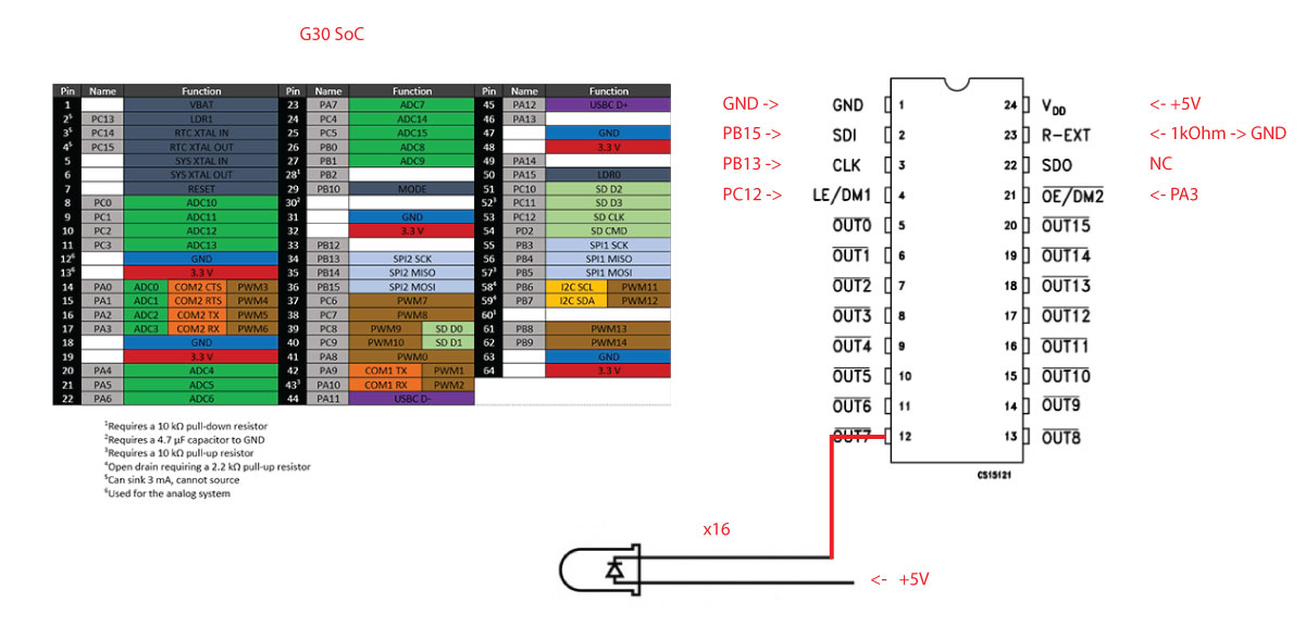
Im not familiar with the G30 nor can i tell from your schematic, but i suppose chip select is PC12 can be a valid digital out pin used for chip select, but then your pic seems to be using it to do whatever LE/DM1 does. It cant be both and for now lets just assume SPI needs a chip select (though it doesnt always)

Now im not sure what OE/DM2 means but if it is Output Enable then it seems you are disabling it by driving it high, that bar over the name usually means LOW enable…

We didnt even get into the protocol that chip needs on the spi to work, but i think you need to first work out the basics.

There are a few good vids on youtube

I think that this chip is better to drive via bit banging shift register … may be easier to use gpio pins to do clk and data in

Ok, ill read that.

As I understand it, LE/DM1 (Latch) needs to go LOW, then I need to transfer some data (16 bytes, or bits I don’t know), and put Latch HIGH again. But SPI in TinyCLR should do that by itself?

OE (output enable) needs to be LOW before I transfer data, and then I can manipulate OE as I am in the loop, I can even PWM the OE to get LED dimming.

I think I left it HIGH in my code while I was trying both LOW and HIGH. But its still not working.

Also im not sure what frequency to set, spi mode and so forth. Nothing of that is apparent from the datasheet, or im just not reading it.

This chip need 16bit bit banging. Put LE low, OE low, then set led bit. After that generate clk low to high then low again. Repeat 16 times, than LE high which will transfer register to leds :thinking:
Set OE high to switch off all the led

Ok so if LE acts as CS than I’m sorry to lead you in wrong direction, that may very well be the case.

But basically the idea with SPI is this, CS gets set to indicate the following action on the clock and data lines are intended for that chip rather than another on the same bus.

Then data is bidierctionally set and read on the 2 data lines, often is the case that valid data is only sent one way, and the clock indicates when to set/read new data. Confusing at first but really it’s very simple.

About the speed, you often have flexibility so I’m the absence of finding the correct data, just use something relatively slow like 100k.

Finally are you sure you don’t need a current limiting resistor on that LED?

Current is limited to 20mA by a 1kOhm resistor on the R-EXT.

Looks to me like you have your LED’s wired backwards

*meh - ignore me…

1 Like

So I got this to work

class Program
    {
        static PwmChannel oE;
        static GpioPin latch;
        static SpiDevice device;

        static void Main()
        {
            var settings = new SpiConnectionSettings()
            {
                ChipSelectType = SpiChipSelectType.None,
                Mode = SpiMode.Mode0,
                ClockFrequency = 100 * 1000,
                DataBitLength = 8,
            };

            var controller = SpiController.FromName(G30.SpiBus.Spi2);
            device = controller.GetDevice(settings);

            latch = GpioController.GetDefault().OpenPin(G30.GpioPin.PC12);
            latch.SetDriveMode(GpioPinDriveMode.Output);

            var gpio = GpioController.GetDefault();
            var button = gpio.OpenPin(G30.GpioPin.PA15);
            button.SetDriveMode(GpioPinDriveMode.InputPullUp);
            button.ValueChanged += Button_ValueChanged;
            button.DebounceTimeout = new TimeSpan(0, 0, 0, 0, 200);

            var pwm = PwmController.FromName(G30.PwmChannel.Controller2.Id);
            pwm.SetDesiredFrequency(750);

            oE = pwm.OpenChannel(G30.PwmChannel.Controller2.PA3);
            oE.SetActiveDutyCyclePercentage(0.1);
            oE.Polarity = PwmPulsePolarity.ActiveLow;

            oE.Stop();

            latch.Write(GpioPinValue.Low);
            device.Write(new byte[] { 255 });
            latch.Write(GpioPinValue.High);

            while (true)
            {
                oE.Start();
                Thread.Sleep(1000);
                oE.Stop();
                Thread.Sleep(1000);
            }
        }

        private static void Button_ValueChanged(GpioPin sender, GpioPinValueChangedEventArgs e)
        {
            if (e.Edge == GpioPinEdge.FallingEdge) {
                oE.SetActiveDutyCyclePercentage(oE.GetActiveDutyCyclePercentage() + 0.1);
                Debug.WriteLine(oE.GetActiveDutyCyclePercentage().ToString());
            }                
        }
    }

Ive tried 16 LEDs for 16 channels but they flicker, ive applied 5V to the positive rail on the LEDs, as soon as I remove all but 6 of them its all good.

It says output current up to 100mA is that for whole chip, or every of 16 channels?
Also guarantees a 20V output driving capability, does that mean I can put 19 LEDs in series (yellow LED 2.1V 20mA) if I provide 20V to the positive rail?

Managed to hook everything up correctly.
But im still don’t know how to turn on 16 outputs in a reliable way.
I get random LEDs turning ON.
From the timing diagram, I think its SPI mode 0.

Can anyone help me out please?

var settings = new SpiConnectionSettings()
            {
                ChipSelectType = SpiChipSelectType.None,
                Mode = SpiMode.Mode0,
                ClockFrequency = 4 * 1000 * 1000,
                DataBitLength = 8,
            };

oE.Write(GpioPinValue.High);
            latch.Write(GpioPinValue.Low);

            latch.Write(GpioPinValue.Low);
            byte a = 0b1111_1111;
            device.Write(new byte[] { a });
            latch.Write(GpioPinValue.High);

            latch.Write(GpioPinValue.Low);
            byte b = 0b1111_1111;
            device.Write(new byte[] { b });
            latch.Write(GpioPinValue.High);

            while (true)
            {
                oE.Write(GpioPinValue.High);
                Thread.Sleep(1000);
                oE.Write(GpioPinValue.Low);
                Thread.Sleep(1000);
            }

Its working now, tried with another G120. The G30 I tried before is somehow broken.