I’m trying to really understand the Device.h file since I’m wanting to port a new board that doesn’t have one yet. But I have some questions for the settings below:
Are these specific to the CPU, or is it dependent on where the device boot pins are wired?
UART_DEBUGGER_INDEX
USB_DEBUGGER_INDEX
#define DEBUGGER_SELECTOR_PIN PIN(D, 0)
#define DEBUGGER_SELECTOR_PULL TinyCLR_Gpio_PinDriveMode::InputPullUp
#define DEBUGGER_SELECTOR_USB_STATE TinyCLR_Gpio_PinValue::High

#define RUN_APP_PIN PIN(D, 1)
#define RUN_APP_PULL TinyCLR_Gpio_PinDriveMode::InputPullUp
#define RUN_APP_STATE TinyCLR_Gpio_PinValue::high_brightness:
Also these seem to be related to the ram size, but where can I find it in the data sheet?
#define DEPLOYMENT_SECTORS { { 0x0A, 0x080C0000, 0x080C0000 }, { 0x0B, 0x080E0000, 0x00020000 } }
Finally is this the same for all STM32F4 series processors, or something else?
#define DEVICE_VERSION ((0ULL << 48) | (10ULL << 32) | (0ULL << 16) | (0ULL << 0))
Thanks!
Most of those declarations are for use from tinyclr and no need to touch
Just pick one of the board (that you have)close to those which are recognised and all you need is to modify part for your needs for
-gpio
-pwm
-i2c
-spi
-uart
-can
Board (stm32f4xx) recognised until now are :
Cerb - stm32f405rtg6
Clicker - stm32f415rtg
Clicker2 - stm32f407vgt6
Fez/Brainpad/Nucleo 401 - stm32f401ret6
Nucleo 411 - stm32f411ret6
Electron/wifimcu - stm32f411ceu6
Quail - stm32f427vit6
@thechipguy many settings are related to specific devices other are tinyclr indipendent. Here you can find other device.h for STM32F4 and STM32F7 boards:
https://github.com/dobova86/TinyCLR_Port/tree/master/Devices
UART_DEBUGGER_INDEX
USB_DEBUGGER_INDEX
are tinyclr defines, although PIN macro depend on your device.
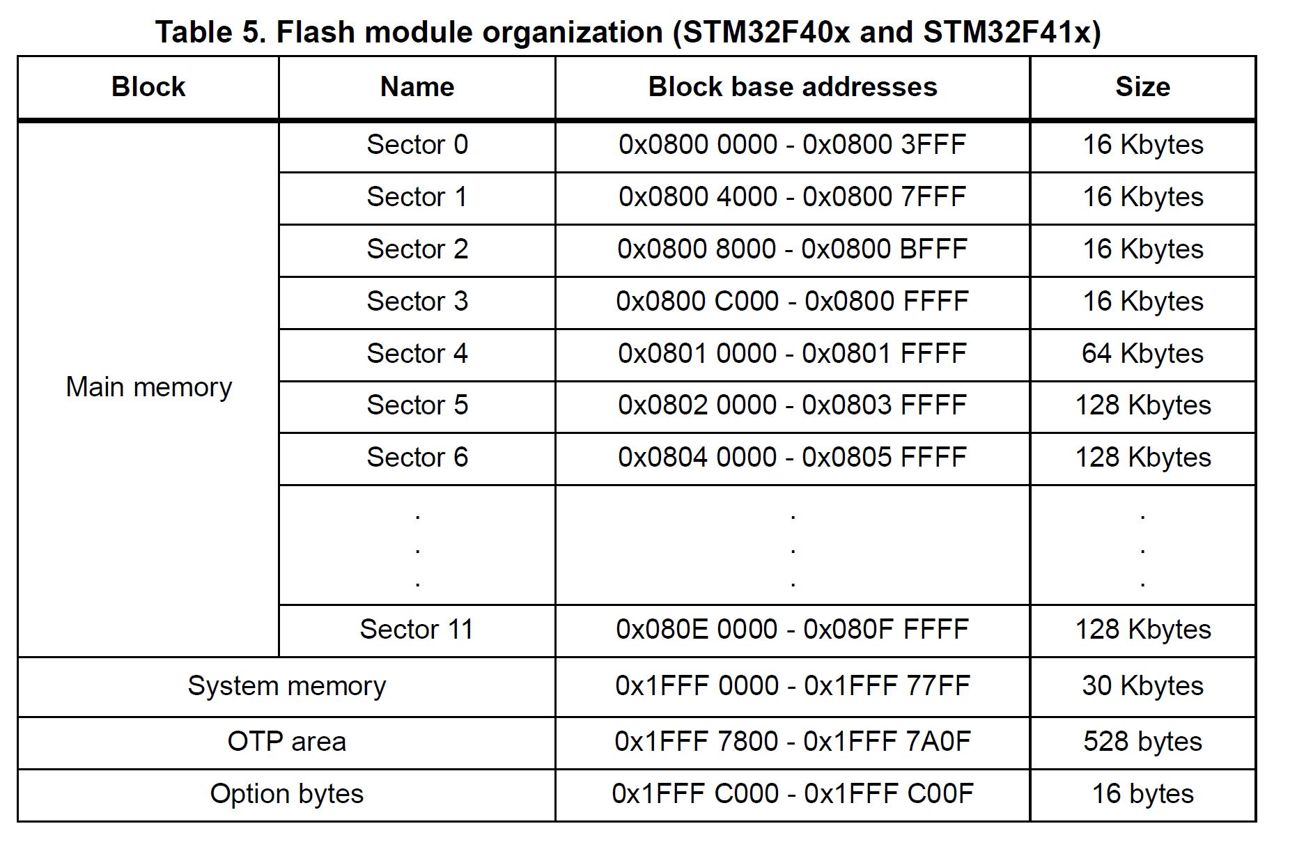
DEPLOYMENT sectors depend from STM32 mcu used. You need to check in the specific mcu datasheet (1MB or 2MB flash, sector addresses and size)
1 Like
Regarding UART_DEBUGGER_INDEX and USB_DEBUGGER_INDEX, those are used to select the controller on the UART/USB provider to use. Which is processor-specific. On the STM32F4, you can see which UART index 0 corresponds to by looking for the UART pin definitions further down in the file.
The RUN_APP_PIN and DEBUGGER_SELECTOR_PIN (and their associated defines) are used to tell the STM32F4 startup file which pins to read to tell TinyCLR if it should run the end-user application or if it should use the USB or UART debugger, respectively.
DEVICE_VERSION is completely up to you. It’s just used to version a specific firmware build. TinyCLR doesn’t care about what exactly it’s set to and just exposes it over the debug interface for your use.
The others in this thread were correct about DEPLOYMENT_SECTORS, it’s specific to the STM32F4 port and corresponds to the physical sectors in its flash. The datasheet for the underlying processor will have more details on it.
Wow thanks for sharing this table, I missed it in the datasheet but it now totally makes sense as to where those values come from. Very helpful explanation of how the sectors work.
Hey John thanks for the explanation. I’m still a bit confused about The RUN_APP_PIN and DEBUGGER_SELECT_PIN. From your explanation, they seem to be used to control when power is applied to the board if VS is launching the debugger or not. While that seems clear, I’m still confused about how to know which pins they are for the device. Are they related to the UART pins of the CPU, or is it more about how the USB/Serial are connected from the computer to the specific device and multiple choices are possible?
All TinyCLR itself cares about is that it gets passed an API that it can read and write to with its debugger. You tell TinyCLR which one to use by calling TinyCLR_Startup_SetDebuggerTransportProvider as we do in the main.cpp file in the ports repo. Currently we support passing a UART or USB provider, but that may expand in the future. Since both USB and UART providers can expose multiple controllers, such as USART1, UART2, USART5, and so on on the STM32F4, you also have to tell TinyCLR which one to use, this is done by the index parameter. Lastly, configuration is used by the USB provider to provide additional configuration information such as VID and PID.
In the STM32F4 provider, we abstract a lot of that away behind the defines in question. If you look in /Targets/STM32F4xx/STM32F4_Startup.cpp in the STM32F4_Startup_GetDebuggerTransportProvider function, you can see how they’re used. DEBUGGER_SELECTOR_PIN is read as a GPIO pin and if it matches DEBUGGER_SELECTOR_USB_STATE then we use the USB provider, otherwise, the UART provider. The USB_DEBUGGER_INDEX or UART_DEBUGGER_INDEX parameter is what gets passed to the index parameter in the above function to pick which controller to use. While the STM32F4 only has one USB in our firmware, it does have multiple UARTs. Which physical pins are used by say the UART interface are controlled by the UART pin defines in your Device.h.
The RUN_APP_PIN does as its name implies. If it matches the state specified by RUN_APP_STATE, then the managed application is executed. If it doesn’t, TinyCLR runs, but it acts as if there is no app present (useful for redeploying to the device if your application is preventing it from communicating).
1 Like
Thank you so much John, that is a great explanation and now it is totally clear.