Hello.
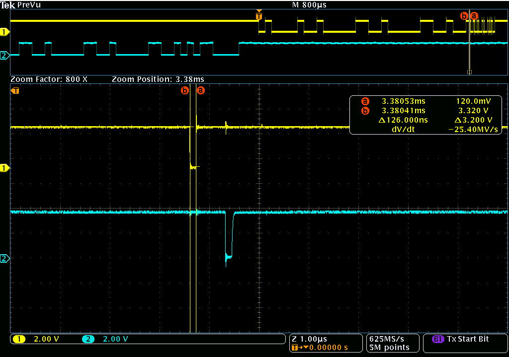
One shot of glitch noise is observed from TX signal of UART communication after B command issue to MSC-MOD20 from the PC side (Windows 10).
B command sequence is as follows.
I M:{CR}
B E1000{CR}
   -> generating one shot of the glitch noise.
To whichever baud rate it’s changed from the baud rate of the default, its width is about 125.5 ns.
Please answer the following.
(1) Would a manufacturer grasp this glitch noise?
(2) Please answer a way and setting to which this glitch noise doesn’t go out.
(3) Please answer a way to avoid glitch noise.
We are not aware of any glitch. Check your power source.
Note you are using a discounted product. Consider using SITCore instead.
I have observed the actual waveform.
Certainly there is an L-interval of about 125ns after the first !00 is sent.
This is probably what is output when UART of STM32 switches the speed, and it is thought to be the specification of STM32.
There is also a description in the STM32 errata that a breakframe may be output regardless of CTS.
There are two ways you can get around this.
-
after you receive the !00 before the speed change, take the first L-pulse (the glitch noise you said) as a signal before the next baud rate, and make good use of it.
-
after receiving the first !00, there is more than several ms time interval between receiving it at the next new rate and the next !00, so ignore any signals during that time.
The best solution is to use the L-pulse as an opportunity to switch to a new speed.
To do otherwise is to ignore the period between !00 being sent at the pre-set rate and !00 being sent at the new rate.
1 Like
I have been using the ALFAT for many years.
Very well done chip.
The solution to your question is simple: Ignore the ACK in the B command.
Take a 200ms break when you sent the B command. That’s all you need to do.
When initializing the UART unit on a CPU such as STM32, the GPIO state becomes unstable. Normally, the baudrate of UART is only set at the beginning and is not changed in the program.
However, ALFAT provides an option for the user to change the bardrate.
When you change the baudrate, the program initializes the UART module. The signal line(TX), which remained at the “High” when initialized, temporarily goes to the Low.
You don’t have to worry about such a small pulse.
If you think you DON’T need it(Glitch noise??), you can ignore it.
2 Likes
Dear Mr. Gus_Issa
Thank you for your advice.
I have no problem with my power supply.
Dear Miss DraganaM
Thank you very much for giving me good advice.
I’m glad that the recognition of the waveform matches.
I will use your advice as a reference.
Dear Mr. AdaRen_China
Thank you very much for giving me good advice.
I can understand that the TX signal temporarily goes low due to the initialization of the UART module in changing baudrate.