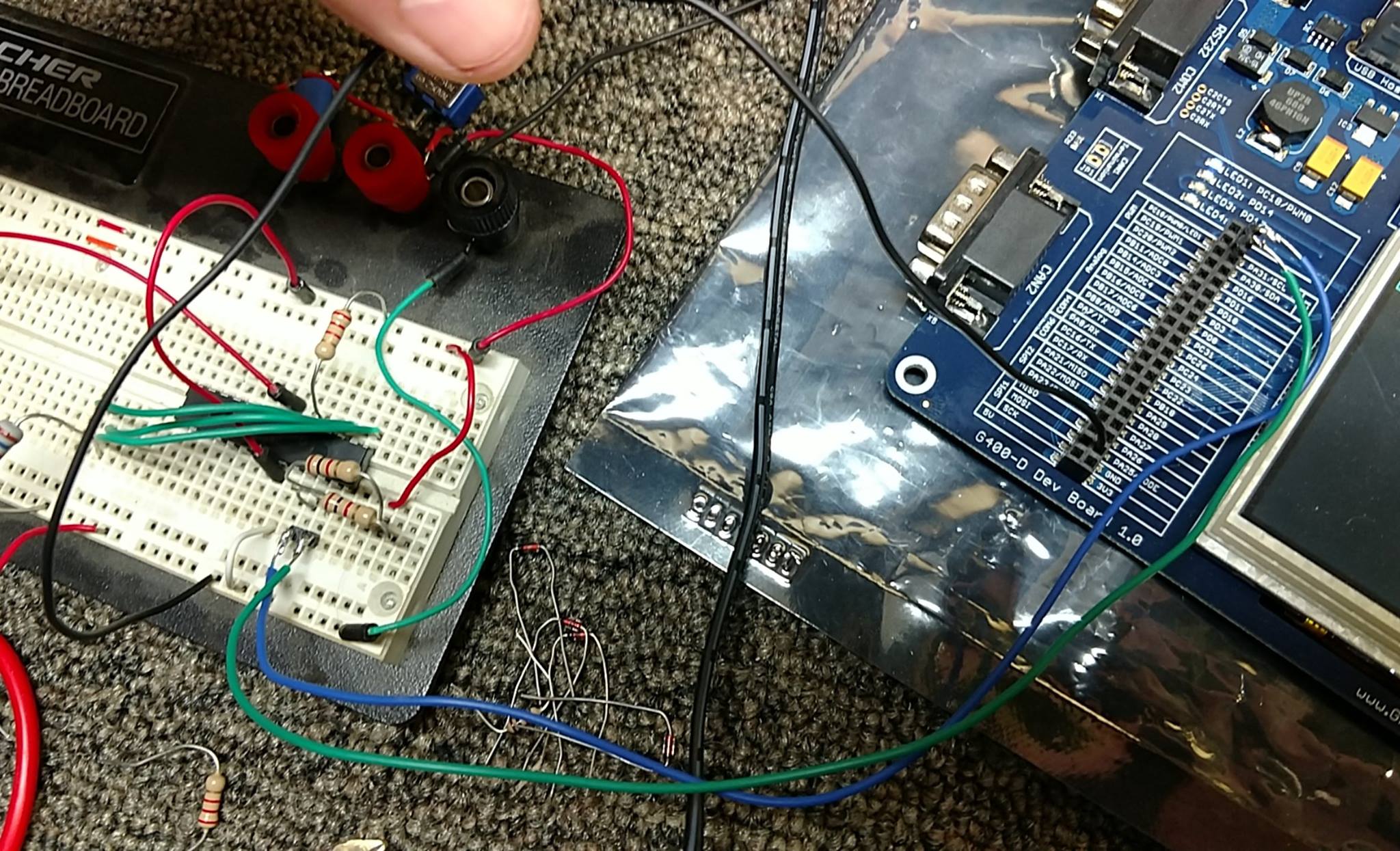
Recently picked up a G400 development board.
Trying to get it to communicate with a MCP23017.
I have SCL and SDA pulled high w/ 2.2kohm (also tried 1kohm per the 23017 datasheet). Address pins are pulled low so address should be 32 (0x20). Reset is pulled high w/ 1kohm, per datasheet. Everything appears to be fine on the circuit.
The program fails to run a transaction and just prints "Failed to perform I2C transaction"
However, I’m not seeing anything coming over SCL or SDA on the scope. I mean, absolutely nothing. Set triggers, nothing is moving. The line just stays at Vcc.
Am I doing something wrong with initialization or transactions? Source is below.
using System;
using Microsoft.SPOT;
using Microsoft.SPOT.Hardware;


namespace MFConsoleApplication1
{
    public class Program
    {
        public static void Main()
        {
            I2CDevice.Configuration con = new I2CDevice.Configuration(0x20, 400);
            I2CDevice MyI2C = new I2CDevice(con);

            I2CDevice.I2CTransaction[] xActions = new I2CDevice.I2CTransaction[3];
            byte[] RegisterNum = new byte[2] { 0x12, 0x20 };
            xActions[0] = I2CDevice.CreateWriteTransaction(RegisterNum);

            byte[] Register2 = new byte[3] { 0x00, 0x00, 0x00 };
            xActions[1] = I2CDevice.CreateWriteTransaction(Register2);

            byte[] Register3 = new byte[3] { 0x12, 0xFF, 0xFF };
            xActions[2] = I2CDevice.CreateWriteTransaction(Register3);

            if (MyI2C.Execute(xActions, 1000) == 0)
            {
                Debug.Print("Failed to perform I2C transaction");
            }
            else
            {
                //Debug.Print("Register value: " + RegisterValue[0].ToString());
            }
            Debug.Print(Resources.GetString(Resources.StringResources.String1));
        }
    }
}
Try address 0x40 or 0x10. I think netmf expects a 7 bit address.
As far as the scope, do you have ground connected? Are the pins high or low?
Sorry for not replying last night, the forum made me wait 8 hours before making a second post.
The 7 bit address would be 0100000, 32 dec, or 0x20.
Which raises the question is your framework converting that to an 8 bit word, or just sending a single bit over the timing channel afterwards? If you converted it to an 8 bit word, you’d have to roll the bits left (<<) and then AND it with 1 or 0 for your least significant bit. Which would be 64 dec, or 0x40 hex, which I also tried, with no success.
Regardless, neither 0x20 or 0x40 worked. 0x10 as you suggested also did nothing.
Like I said I set up my scope and nothing is happening on the line, and i2c transactions simply fail to process. Scope is calibrated, and I can clearly read a PWM pin with no issue. The i2c clock and data lines are reading ~5v (my supply voltage), pulled high by the resistor to supply, with a slight ~60hz noise ripple coming from somewhere. (I’ll add a tantalum cap to filter that out later, it’s very minor)
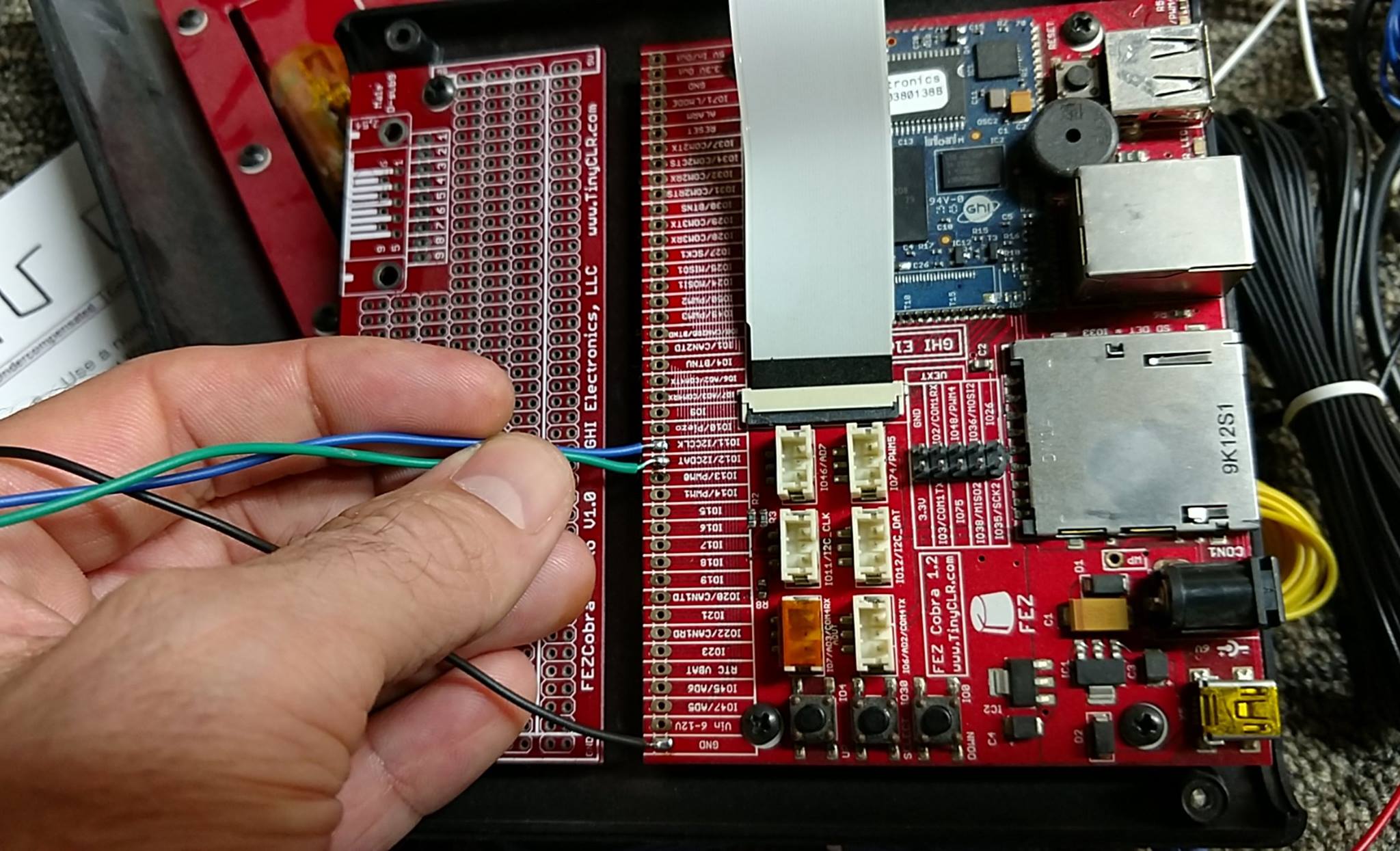
I have an old FEZ Cobra w/ an EMX processor sitting here. I’ll get it upgraded to MF4.3 this afternoon and see what happens from there, with the exact same code and circuit.
1 Like
Sounds like you are doing everything correctly so I am not really sure why!
Solved the problem. I was only using 2 wires between the G400D dev board (SCL/SDA).
When I connected GND to my breadboard, connecting the ground planes, everything started working perfectly.
I thought i2c only required 2 wires? It appears as though I’ll have to connect modules with 3 (clock, data, ground)?
2 Likes
Man I chased my tail for 24 hours on that. 
Now that data is being sent the triggers I set function.
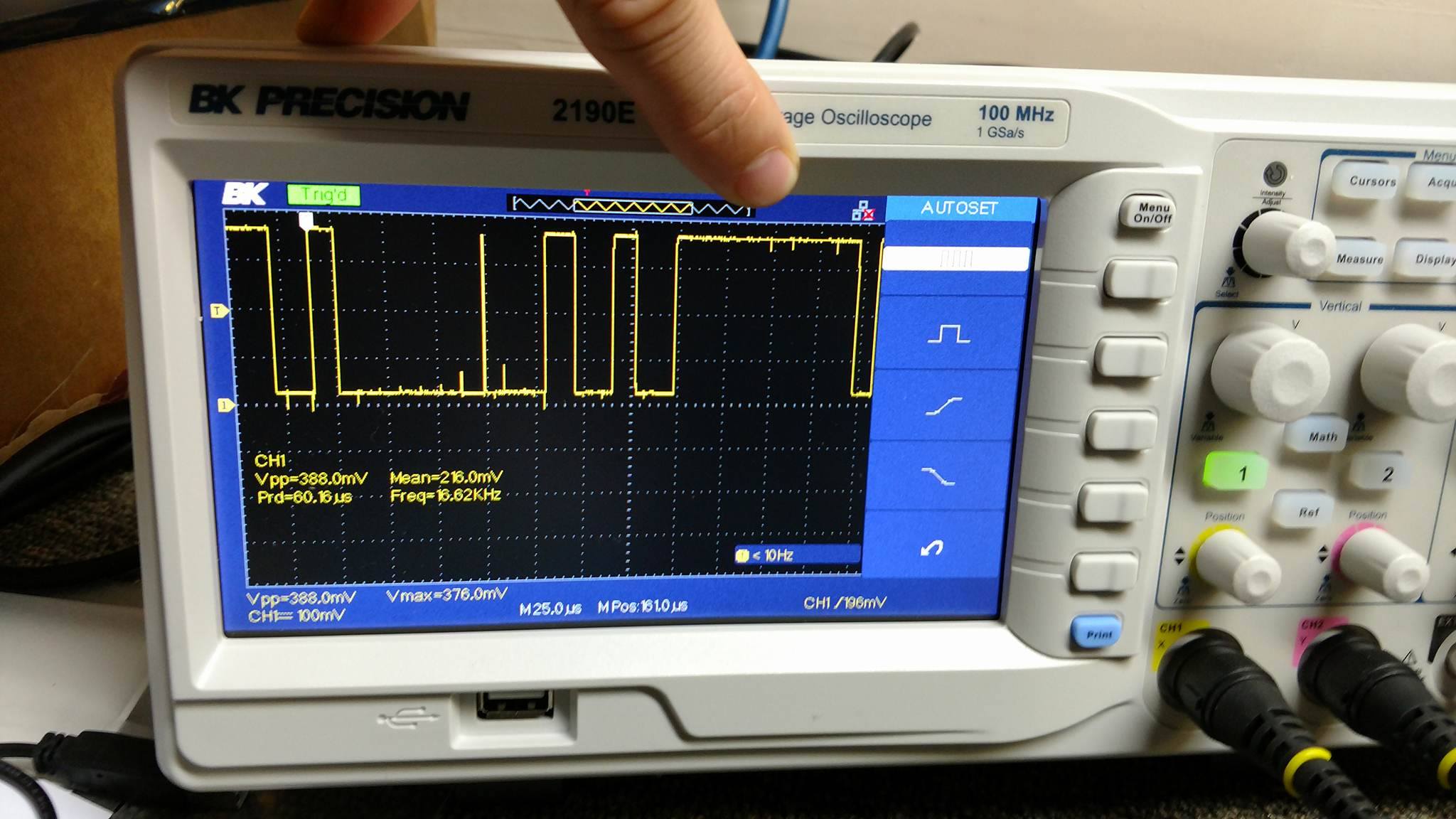
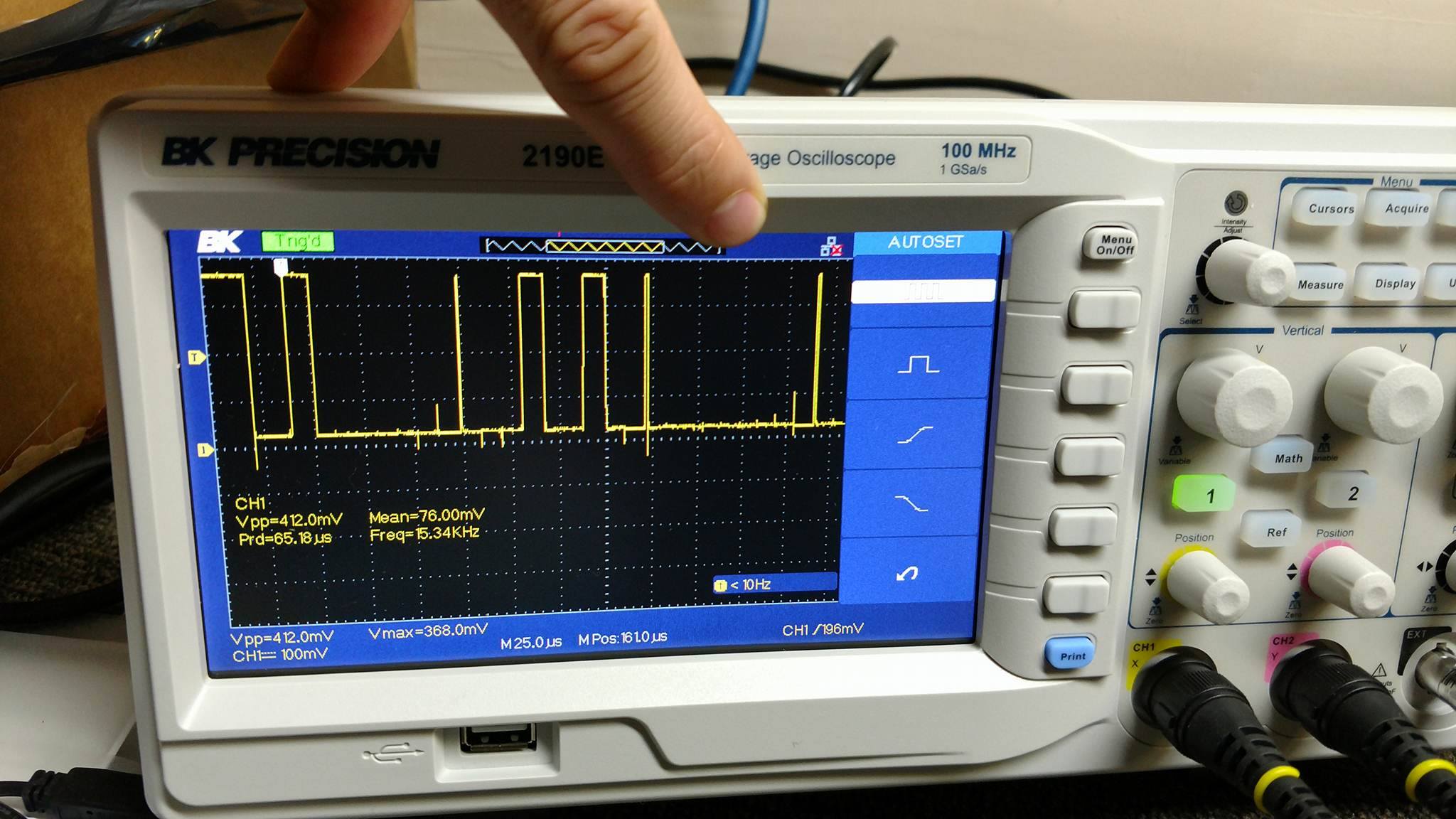
I adjusted the data clock down to 100khz so it’s easier to see;
SCL probe:
SDA probe:
the program was changed to set bank A on the MCP23017 to 0xFF and 0x00 (all 8 outputs on or off) on a 1 second timer
Byte 2 0xFF
Byte 2 0x00
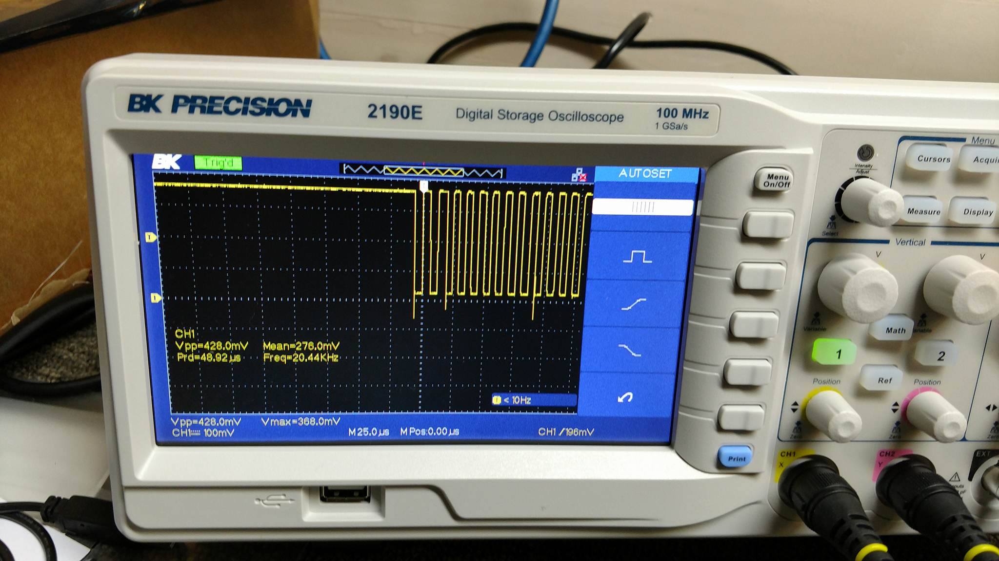
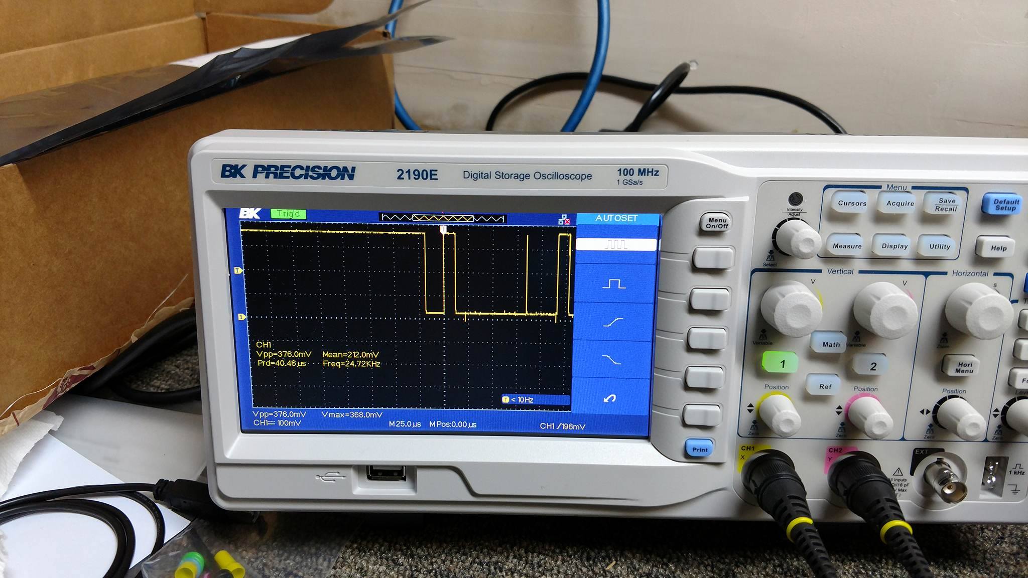
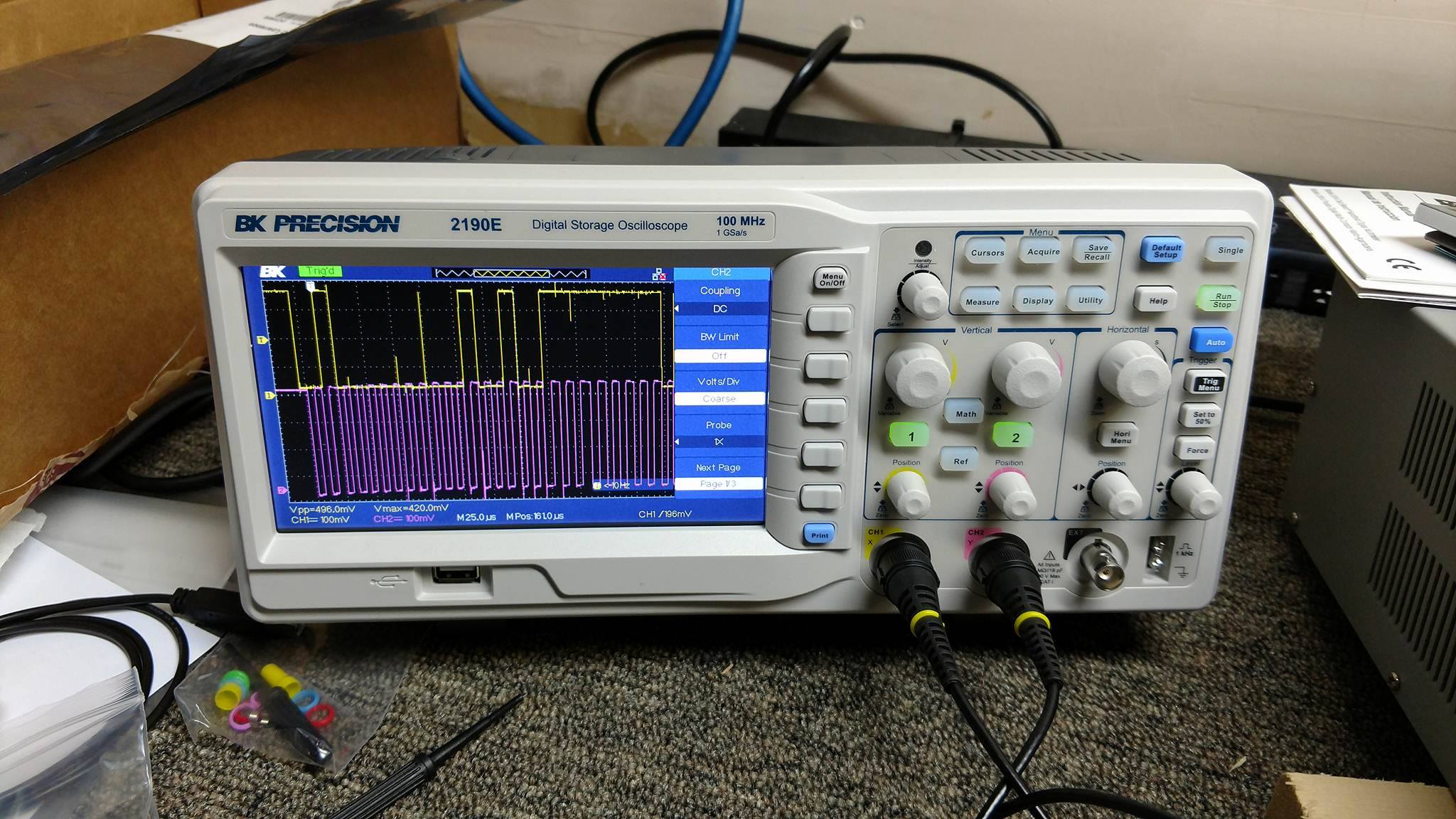
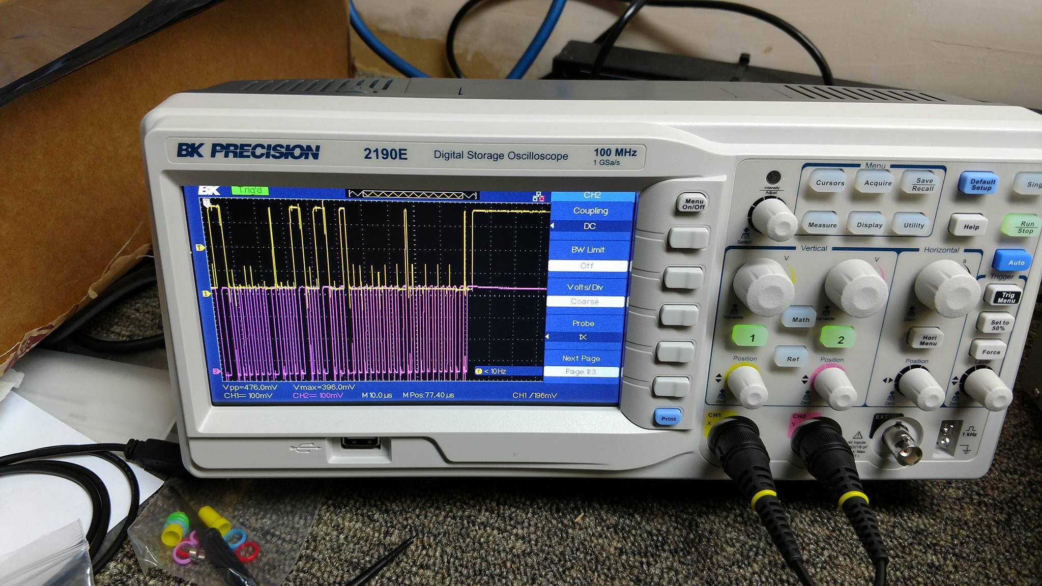
Odd. When I crank it up to 400khz and set the scope to 10.0 microsecond, you can clearly see timing clock is not consistent;
Here’s a couple captures. Vastly different timing.
Any reason why the G400’s i2c clock should not be consistent at 400khz?
@ trent1098s - In every system you have to connect the grounds together. When they said that It only requires 2 lines, GND and VCC are understood.
John,
Currently I have the circuit on the breadboard containing the MCP23017 running at 5v from my bench power supply. Should I connect that 5v rail to the 5v header on the G400 dev board? Or should I be supplying the breadboard from the 5v line on the dev board?
While testing I wanted to isolate the supply rail on the breadboard in case I did something dumb. Didn’t want to risk toasting the (comparatively expensive) G400-D Dev board while mucking around with a $1.00 i2c GPIO chip. 
@ trent1098s - However you were powering it before should be fine.
Thanks. Everything seems to be working great now. I left it running for 24 hours, no problems.
When I turned on my scope (with the leads still attached, whoops) it broke something. Had to reset the G400 for it to start working again. Made a mental note not to do that again. It was strange, still sending the i2c data (could see it on the scope once that powered up) but the MCP23017 chip wasn’t responding. Tried shorting it’s reset pin, tried power cycling that whole breadboard, didn’t come back up again. I had to reset the G400 for it to start working again. Not quite sure what was up with that.
But the original issue that caused me to open the thread has been resolved, so can consider the issue closed (was ground not connected b/t g400 dev board & breadboard that was the root cause).
Still the odd thing where timing isn’t the same - seems to time faster when it’s sending 0x00 bytes and slower when it’s sending 0xFF, not sure if that is by design. Doesn’t seem to be causing any issues and it’s just a 1 µm difference so … not too worried about it.