So my design is coming along nicely, all hardware selected for the most part. Stuck on getting the STM L6470 motor controller to work in my prototype though. I am using the dSpin class to control it but for some reason, when I run my code, it cannot set the parameters for Khold and Krun - I get notifications stating registry 9 setting to 1 returned 0 register 10 setting to 128 returned 0 along with several other registry errors. No motion from the motor. Everything should be connected correctly I have checked a solid 10 times especially after catching the first chip on fire
Any suggestions?
Note: Created a new topic because it wasn’t letting me reply to the old one at the time.
Yes the chip burst into 2 flames - one on each of the two pins that shorted. Had a mess of wires and one came lose from the 3.3 V supply and I accidentally plugged it back into the 12 V motor supply. 3 days worth of work nice and crisped. I rebuilt it faster this time though and labeled my groups of wires - its just on a breakout board attached to a breadboard right now (****ed up the first two controllers just trying to solder wires on them haha the pins are so damn tiny!)
These things need built in current protection from my newbness,
I now have all the registers setting to numbers other than zero - they are all returned half (-1 if odd) of the desired value being set. I was told this is a timing issue, maybe with how chip select is supposed to be pulled high(?) after each bit is wrriten?
I will show you a schematic in a few mins I have to edit this one a bit, I don’t have all the same capacitors or resistors in my circuit - my chief is an electrical engineer, he tells me how to do all the power supply connections.
Not sure what you’re working with but are the registers storing a twos complement binary value?
From that datasheet;
9.1.1 ABS_POS
The ABS_POS register contains the current motor absolute position in agreement with the
selected step mode; the stored value unit is equal to the selected step mode (full, half,
quarter, etc.). The value is in 2’s complement format and it ranges from -221 to +221-1.
At power-on the register is initialized to “0” (HOME position).
Any attempt to write the register when the motor is running causes the command to be
ignored and the NOTPERF_CMD flag to rise (see Section 9.1.22 on page 55)
You have to convert a 2’s complement binary number before you use it.
Ok that went a little over my head, mostly “You have to convert a 2’s complement binary number before you use it.” I am using the dSpin_Move command to attempt motion. Does that still involve the ABS_POS register?
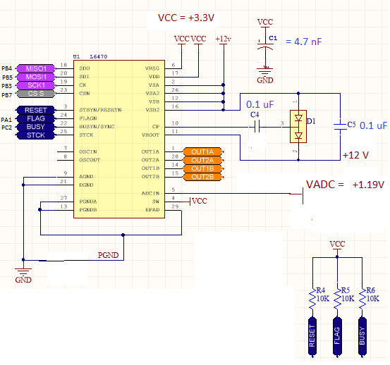
I changed a few things in the code and now most of the registers are setting correctly, except for 9,10,11,12,23, and 24 (register 9 and 10 did accept the first value but setting them again in the loop to run the motor. I am not sure what I did that fixed it - I changed the clock to 5 KHz and also changed the SPIconfig parameter Clock_Idlestate from true to false. Whatever changes I made stopped it from being stuck as BUSY - I think the clock timing was off so it wasn’t communicating properly. Not sure about these last few registers that are being difficult. Here is my schematic, adapted from someones that I am following, hopefully they don’t mind. I used paint to change it because I don’t have the program to do it yet - my supervisor told me to use those capacitor values not sure why but he knows better than me.
I need help finding the back emf and all that nonsense of the motor to set all the K values on the L6470. I have the calculator thing from STM but you have to manually find the back emf with an oscilloscope which I am unsure of. Also I am not sure what the rest of the constants should be such as
The motor does nothing until 8 V then it starts to vibrate and voltage in my protection circuit spikes to 20 volts. Measuring the leads going to motor I only read like 1.5 V. Can’t figure out how or why. Could any of the K values I sent or bemf compensation be off? Or does that sound like a bad connection? Hopefully I didn’t fry this board too.
The only thing I can see missing is decoupling on VDD and VREG but this might simply be that you are not showing these. Same for VS, there should be a suitable reservoir cap on this. Again, just night not be shown.
My boss insists the capacitance value does not make a difference…his experience doing this for 10 years hold some credibility so I want to double check the pins and software before I go through the effort of busting out our tiny PCB capacitors. What registers would affect the phase output pins on the driver? The krun, khold, kdec, and kacc have been set to between 50% and 80% with no change in output voltage. The voltage spike only occurs when the power supply reaches 8 V, then the motor begins to vibrate and the voltage on C5 spikes to 15 V.
Since ABS_POS returns a signed integer in two’s complement, yes, whenever you read it you need to deal with that.
Fortunately this is a simple matter to convert the number as I indicated. However, I see now that you’re using a library for the stepper motor controller (you didn’t write that yourself) so you have to trust the author handled this for you. (I thought you were writing the library yourself, my mistake).
Twos complement is something you should learn regardless as at the low level you work with, it’s very important.
This is taken from an Analog to Digital Converter library I just finished for a linear chip. I’m including the full function because there’s a lot of bit level manipulation of the result - but the relevant part is the three lines of code under “//manual twos complement conversion”.
(Ignore the other stuff)
Point here, is whenever you run across “Twos complement” in a datasheet you do need to handle it properly to get a signed integer result from the raw data. In this case I’m assembling two bytes from three, where there’s status flags, a manual sign bit, and other stuff that’s not relevant. But those two bytes are returned as twos complement, so must be handled, before further manipulation and a result can be obtained.
   public void DecodeResult(byte[] inputbuffer)
    {

        int SIG;
        int MSB;

        int val0;
        int val1;
        int val2;

        int result;

        SIG = (inputbuffer[0] & 0x80) == 0x80 ? 0x02 : 0x00; // sign flag is first bit returned
        MSB = (inputbuffer[0] & 0x40) == 0x40 ? 0x01 : 0x00; // MSB is second bit returned - although it does not appear to function as MSB, but rather only a flag

        if (SIG == 0x02) { _SIG = true; }
        if (MSB == 0x01) { _MSB = true; }

        if (_SIG && _MSB) { _Fault = true; _Overvolt = true; } //overvolt condition

        val0 = SIG | MSB; // store combined for reference later


        int bit1; // temporary holders for transposition of MSB to LSB on reassembly of output code
        int bit2;

        val1 = (byte)((int)inputbuffer[0] << 2); //shift left 2 bits as we stripped those

        bit1 = (inputbuffer[1] & 0x80) == 0x80 ? 0x02 : 0x00;
        bit2 = (inputbuffer[1] & 0x40) == 0x40 ? 0x01 : 0x00;

        val1 = val1 | bit1 | bit2;

        val2 = (byte)((int)inputbuffer[1] << 2); // we had to shift this over two and copy msb to lsb on byte 1, now do the same for byte 3

        bit1 = (inputbuffer[2] & 0x80) == 0x80 ? 0x02 : 0x00;
        bit2 = (inputbuffer[2] & 0x40) == 0x40 ? 0x01 : 0x00;
        val2 = val2 | bit1 | bit2;

        //manual two's complement conversion
        result = (val1 * 256) + val2;
        result = ~result;
        result += 1;

        if (SIG == 0x02) { result = ~result; }

        if ((SIG == 0x00 && MSB == 0x00) && (result == -0xFFFE)) { _Fault = true; _Undervolt = true; } //Indicates an undervoltage condition, below -FS

        _ResultFlags = (byte)val0;
        _ResultMSB = (byte)val1;
        _ResultLSB = (byte)val2;

        _DecodedResult = result;

        double voltage = ((result) / 65535.00);
        voltage = voltage * (Vcc / 2.00); //Vcc / 2 for range
        _InputVoltage = voltage / GainDivisor(_Gain); //gain divisor

    }
I increased the power supply capacitors significantly - no change. What is the minimum voltage the charge pump pin show be outputting and how is this adjusted?
Also what is Clock_IdleState in the SPI Config? If I set it as true then the registers don’t set properly.
Also is there a minimum frequency on the for the clock?
What could possible stop the driver pins from outputting the supply voltage? they are just outputting logic voltage. Voltage on Vboot is more than enough. Something inside the driver is stopping the voltage change