Fez Flea and never ending Interrrupts

I keep getting multiple interrupt calls, so much so that I had to implement code to try and debounce the input.

flag = GpioController.GetDefault().OpenPin(SC13048.GpioPin.PA0);
flag.SetDriveMode(GpioPinDriveMode.Input);
flag.DebounceTimeout = TimeSpan.FromMilliseconds(500);
bool flagLatched = false;
flag.ValueChanged += (s, e) =>
{
    if (e.Edge == GpioPinEdge.FallingEdge && !flagLatched)
    {
        flagLatched = true;
        flagResolutionThread.Resume();
        
    }
    else if (flag.Read() == GpioPinValue.High)
    {
        flagLatched = false;
    }
};

Should I be using the pull up or pull down resistor?

can you try this:


flag.ValueChanged += (s, e) =>
{
    Debug.WriteLine(e.Edge.ToString());
};

The requirement for a pull up/down resistor depends upon the characteristics of the signal source.

If the signal is supplying proper zero and one voltages, and switching times within specifications, then a resistor is not required. Too much time in the forbidden zone, between one and zero, will cause issues such as you are seeing.

But, for a definitive answer, you would have to tell us how the signal is being produced.

What a truly baffling result. I added a counter as well.

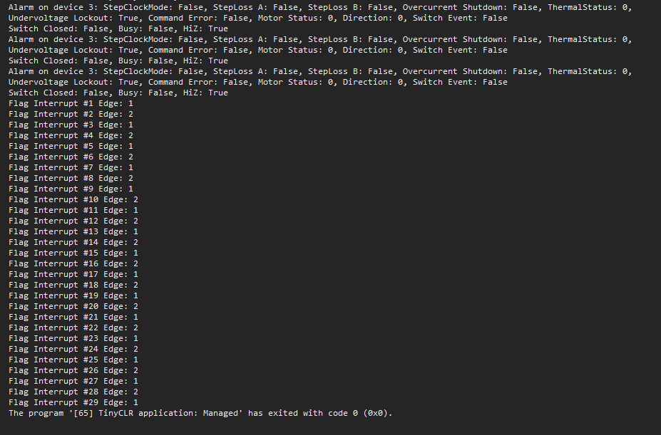
The PowerStep01 stepper drivers are producing the signal; Active Low. Are we thinking that they are constantly toggling the Flag pin? I’d have to break out the scope to find out (sigh).

EDIT: The datasheet says its a latch and does not toggle continuously.

Sounds like a good plan…

Chat GPT says that TinyCLR is internally polling the signal and producing the interrupts. Is that true? It could save me from having to pull out the scope.

1 Like

Lol and how would chat gbt know what is happening inside closed source code?

That’s what I wanted to confirm. Cuz you’re using the hardware to detect transitions right?

Scope time!

Something was wrong with the board. I’ve reverted to a previous solution.

I’m getting 1 flag interrupt now, which matches what I see with the status lights.