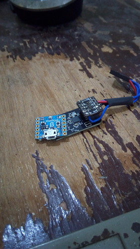
I’m having trouble with a I2C device (the gadgeteer gyro module). How does one go about diagnosing this bus. I’m not sure what I’m looking at on the Oscilliscope.
hmmm, are you doing this with some sort of Storage CRO or siginal analiser, be pretty difficult otherwise, unless really slow clock.
Whats it not doing?
What happened after you tried doing the most simplest thing and read a register (Maybe WHO_AM_I)…can you see it transmit data back?
Any ACK’s going back at all?
Do you think its a timing issue?
Is VLOGIC being set withing the timing specs?
AD0 I2C Address correct? Low = B1101000 ADR High = B1101001 ADR
Are there def. external pull up resistors on SCL and SDA lines?
https://www.sparkfun.com/datasheets/Sensors/Gyro/PS-ITG-3200-00-01.4.pdf
I think this is it?
Yep, that’s it. So you must always have external pullups with I2C? How did Gadgeteer do it? (since it’s a Gadgeteer module). Looks like I have a few things to try. Yes it’s a DSO Scope (Rigol).
I think most of their dev boards and things had them built in.
Not sure what board your using, but as I was reminded by Brett this week, there is always a GHI Circuit to go find for your board and have a look to see.
Id say its there if ALL GHI stuff your using, just wasn’t sure…
yes, most GHI mainboards (and honestly, most commercial boards I have) had I2C pullups in place. If you’re doing custom board, you need to put them in place (or not if you don’t ever expect to care about I2C)
Yes Pullups are required, but also be careful not to add 10k on each i2c board when adding a lot of them. At a given step the 10k in parrallel will finaly give a tiny ohm value, less than required by the i2c standard.
Best is to put a couple on the base board
Shame you didn’t get the decoder option for free when you bought the scope.
TEquipment have it on sale but might be out of your price range. It works so well and makes working with bus based systems a breeze.
https://www.tequipment.net/Rigol/SA-DS1000Z/Options/
For a much cheaper option for I2C at least, the Bus Pirate is a good choice. I have one and back when I got it there was no GUI but looks like they have one now.
the decoder options are enabled for free when you buy the scope and have about a 30-hour run time before the feature becomes disabled as well.
@Dave_McLaughlin, Yea, I have the decoder.
Would this be of any help? Seems to cover the basics.
so, lets start at the beginning… what do you think is happening and what do you see in software… and lets go from there.
I use this guy:
It is much more expensive but I love it so much. If you expect to debug a lot of hardware it’s totally worth it.
(was sick yesterday, so no work done)
I think the cable is too long, and the problem is noise.
sigh
ah thats no good - hope you’re better now…
You’re the expert in that “challenge” aren’t you? ![]()
@Bret, Yes.
So what is the max practical length of I2C? Is there some other way to get data from a sensor over a meter away?
The top search in Google claims that someone successfully used an I2C bus of 100 meters by running at 500 Hz. Lowering the clock speed should help in all sorts of situations where noise and distance are problems. If you can’t lower the clock speed then maybe you can check to see if impedance matching might help? Termination resistors at the load are used to match the output impedance of the driver in an effort to reduce the amount of reflected signal. I’m not sure what this looks like when both sender and receiver share a line and just sink current. Maybe it doesn’t apply to I2C I’ve never checked.
More common than issues with reflection are issues with higher-order harmonics on the clock line. There’s no such thing as a square wave and a lot of noise is generated by our digital devices creating very squarish waves. You can filter these out with a little RC filter near the generator of the clock. You must choose an RC time constant such that the clock signal becomes stable in time for the reading of the bit aka must still oscillate fully at the baud you specify.
This stuff used to drive me crazy because I didn’t understand. I felt I could never understand until I just tried it! 
