DC Grounding of Multiple SwitchMode Power Supply interconnected systems

Ok, sorry this is Totally off topic, but just after some general thoughts.
I know this is one of those questions that is impossible to describe in words. Appologies!

Got a situation where a project Ive heard of third hand has had a major failure and blown up several inter connected dataloggers and analogue multiplexers, that run off multiple switch mode power supplies that do NOT have their secondary output DC GRD’s commoned.
The analogue inputs to the Dataloggers are high impedance inputs, grouped in channels,but do have a max limit of ±30V DC between any pin.

My question is, (if you can picture it in your head is) if you have two switch mode power supplies lets say they are 24v DC and 30v DC supplies, where the DC GRD’s of both supplies are NOT common/linked, but they go back to high impedance input channels on a DataLogger which has a limit of max ±30V DC potential different between any input pins (eg any channel).

Is it possible the DC Grounds of either switch mode supply, could float high enough to mean they exceed the maximum voltage differential limits of the input/channels? Sorry I know this is one of those annoying stupid questions in just words!!!

But I guess the grux of what Im saying is, if you imaging two non DC GRD connected Switchmode power supplies, that do NOT have their secondary DC GRD connected to primary chassis ground for example (like PC power supplies do, which means multiple PC power supplies are common DC GRD’ed) , can the 0VDC GRD of say the 30vDC secondary output float way above the other 0VDC 12cDC secondary on the other supply? Thus causing the DC GRD connected to one channel on the datalogger being WAY above the other DC GRD of the other supply, meaning it exceeds the Max 30 V difference limitation!

The switch mode transformer in both supplies physically isolate the primary and secondary sides. Inductance between the two coils is the majority transfer of energy between the primary and secondary coils, which for analogy sake produces the output. But there would also be a capacitive transfer between the two side of the transformer which might float the DC GRD to a potential relative to the other supply?!

Can this make the DC GRD of the two supplies float to different potential IF referenced between the two 0vDC output pins on both supplies?

So between 0VDC and +12VDC or +30Vdc output the supplys, obviously the potential between 0VDc & output is +12VDc and +30VDC respectfully, but how about the potential difference between the two ‘floating’ DC 0V DC Grds, Will they float to different potentials, that if connected to a third party device like a data logger channel inputs (bunch of OpAmps and A/D converters basically) could be a over voltage issue ???

wow… ok said it…
I know thats impossible to understand so I think I have another analogy, but tired, its late so might be dribbling rubbish…

Imagine two independent switch mode power supplies +30vDC output that connect to the inverting and non inverting inputs on a single chip Quad OpAmp different channels. Which has a 30v max limit between any of its inputs.
Could the floating supplies through what ever means cause a over voltage limit exceed of its inputs because they are not DC Grounded together and floating?
I know this is not a normal configuration, but this is what I believe they are doing above.

Are they connected to the same grounded outlet?

1 Like

and are the power supplies actually using that ground? I’ve seen many a AC-DC converter that might have an earth pin in the AC plug, but they are still not earth referenced.

I think the clear answer here is yes, since they share no connected reference, they conceivably could produce voltages that are greater than the expected voltage if the ground references are not related. 30v on one supply could be equivalent to 35v when referenced to the GND on a different supply (although unlikely to be that different, I would expect - maybe 2v is more realistic, but there’s nothing stopping it).

1 Like

Thanks John,

In my ‘other analogy’ example yes you could imagine they are, BUT not with Secondary output side DC GRD connected to Mains Earth, as that would then common both floating power supplies to each other through the mains earth grounding.

In the real life situation (this is where things get complicated) as one of the Supplies is 240v Mains, the other supplies are a mix of DC-DC up converters.

Thanks Ben, yeah thats what Im thinking.
But not sure about over time actually how ‘bad’ this float difference could get, enough to start blowing gates up?
Wonder if it could go up beyond 20-30v over time…

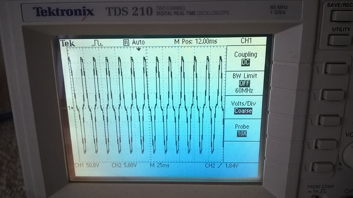
Just out of interest check this out, for a crappy floating DC output Switch mode power pack (working, all good)

CRO just to DC GRD, NO LOAD (and yes sure, if you put any load on it, even finger, there is tiny current flow before the noise is brought down to zero!, but in my head Im going!!.. um if this thing was driving a circuit connected to a datalogger, and was effectively cut off for a time, becuase it was sitting behind some high impedance MUX’ed inputs, and then the MUX connected it back into the DataLogger, ummm, what happens t the poor mux & logger for that first few milliseconds?)

A more decent HP laptop supply, was about 5v pk-pk ripple, that seems totally acceptable to me and more like what I’d imagine to ‘see’

Its stuff like this that makes my head spin when you start over thinking it!!! As I do Nothing is simple!!!