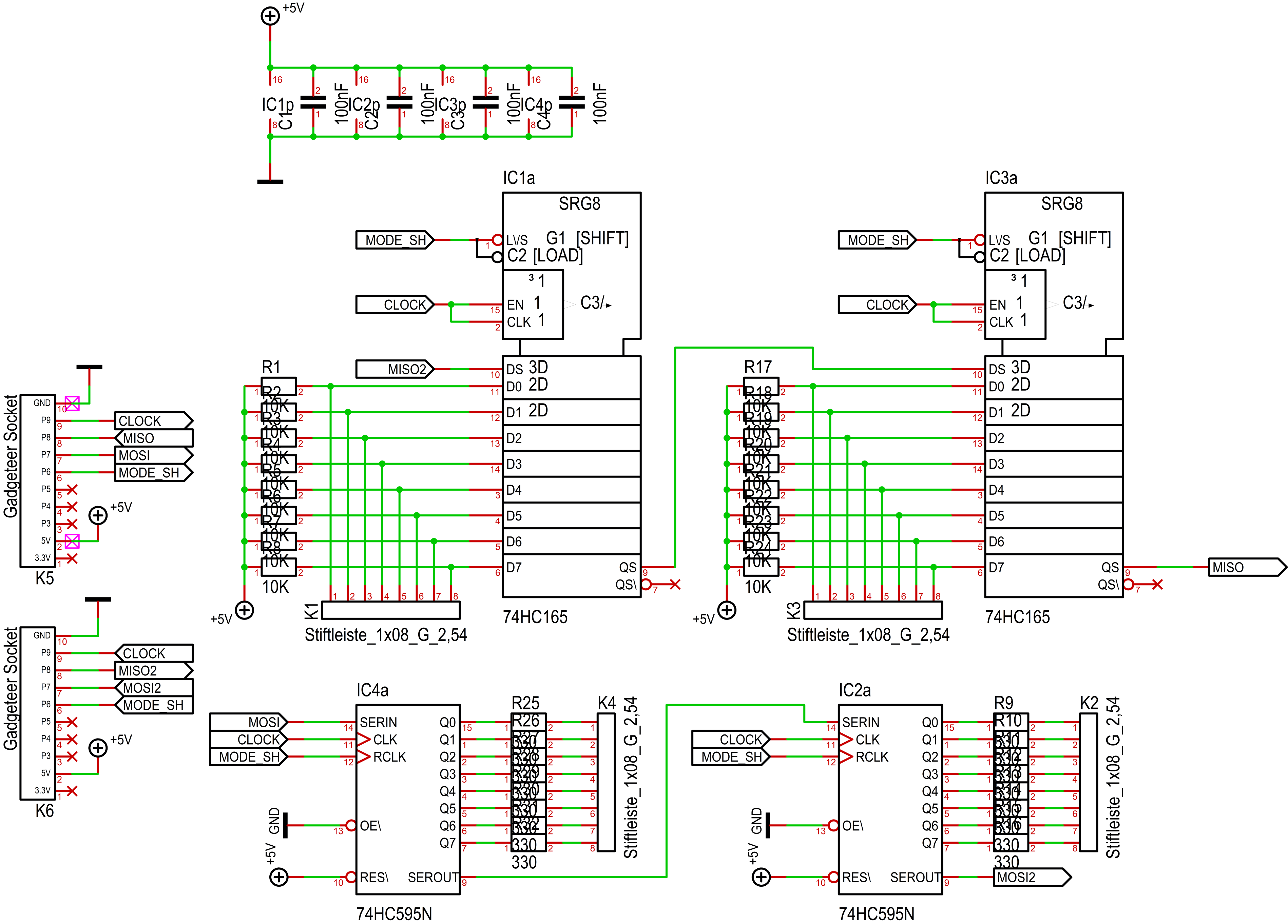
I wanted to try out ordering a PCB on seeedfusion and had some space left on the standard 10x10 board size. So I came up with the idea of creating a simple pushbutton input / led output gadgeteer-“compatible” module. In my recent projects I had used a couple of MaxOs, liked them and thus decided to take that as a starting point and add input myself using the “dual” of the 74HC595, namely the 74HC165 for that purpose.
This is not my first PCB design, but I am far from experienced and would feel a bit better if someone who has experience could have a look on my design. And maybe point out some things that I should avoid or do differently?
It seems I cannot upload PDF files here, so I’ll have to link it. Hope that’s okay: Dropbox - InOutModule.pdf - Simplify your life . (I could also provide gerber files if needed). If you look at it, on the left you will see the inputs, on the right the outputs, on the bottom the “upstream” gadgeteer connector (towards the SPI master - mainboard), on the top the downstream gadgeteer connector.
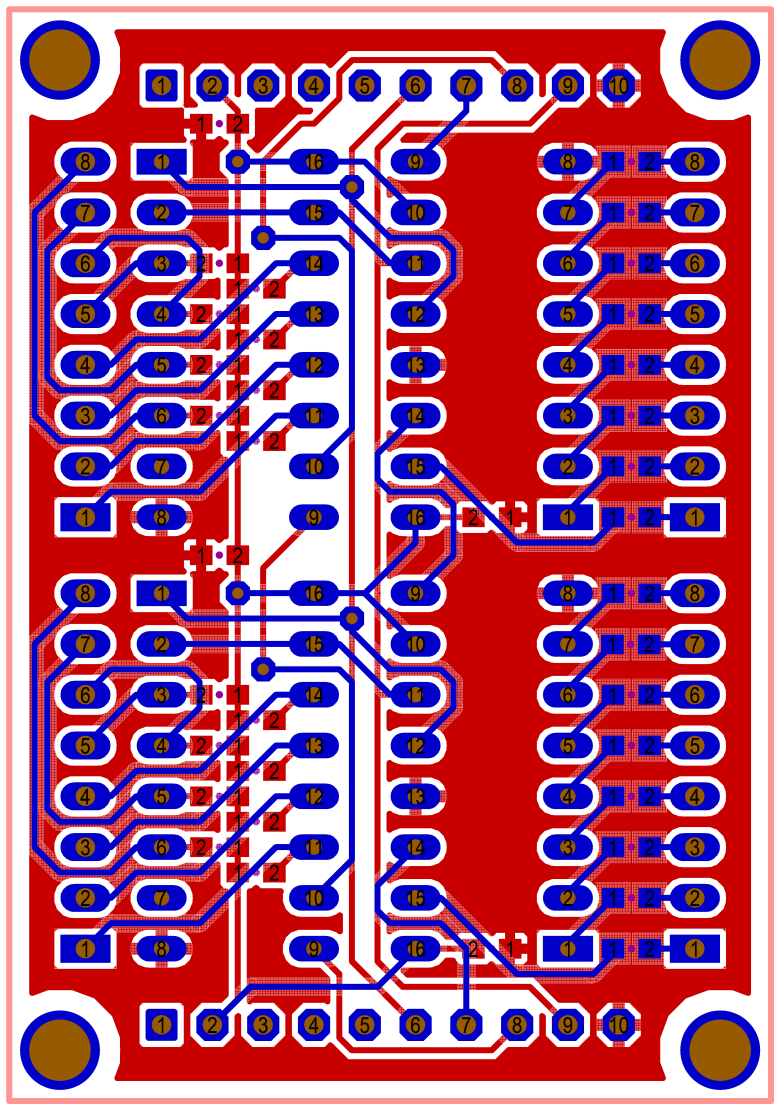

What I am looking forward is to get comments about the layouting/tracing in general, and maybe have a close look at the ground plane as well (first time I used it).
Some points/“requirements” worth mentioning - if you ask yourself why the heck it looks the way it does:
- The module should be a) chainable with another of the same or b) with MaxOs (I typically have many more outputs than inputs)
- The push buttons will connect to ground, so a pull-up resistor on board is needed for every input
- I don’t have easy access to gadgeteer sockets but i intended to use those mini breakouts together with a 10 pin male header as a replacement
- It needs to be hand solderable given my moderate soldering skills and tools (i.e. no hot air station), therefore I chose to use through hole components for the ICs. I have already successfully soldered 0603 so those are alright for me, but if it has it’s legs too tight together I won’t be able to catch it
- The module will use only 5V and that’s intended. The MaxO powers its output from 3.3V and it’s a bit hard to find the right leds cheap given the preinstalled 330 ohm series resistors. Besides, 5V comes directly from the external supply and thus does not have to be linearly regulated down and produce heat
- I applied the default settings for trace width/distance that I used on my previous boards. seeed probably can deal with a lot thinner traces but it’s ok for the moment like that
- I use Target 3001 which has some quirks and does, in my view, not use good fonts for PCB printing. It’s anyway better to not look at the silkscreen layer yet as I have not put much effort into arranging component texts
- The final board will have 32 inputs and 32 outputs, that is, I will repeat the 74HC595/74HC165 “stage” two more times then
I would really appreciate any feedback!