Hi,
I’m pretty new to this stuff and have been looking into the electronics for a reprap system. Traditionally this is arduino based, there is also a rc2c based system. The rc2c based system provided a far faster chip with more memory and a more effient machine in production value.
As the fez boards are a step up in these directions and I notice you can get stepper driver boards for them I wondered how viable the system is.
The first complication is the stepper boards. They are driving two motors per board. Their advantage is providing 3amps, which is better than the standard 2, but is that per motor? Do they provide separate logic for each motor to move independently or both the same. I’m presuming independent logic.
The second complication is software and hardware control. Standard Cnc using g-code. Someone did mention attempting to use it.
3d files are converted to Gcode for the arduino. So it’s all g-code.
Essentially then it’s a question of what programming language controls the stepper motors in fez and what limitations are there to the driver boards?
How many driver boards could a for example fez hydra handle?
Is this all within simple bounds of the boards or am I missing something.
Are there any good examples of stepper motor controls used in projects? Preferably with someone I can ask questions to
Regards,
James.
Hi James
Welcome to the the community.
There are lots of resources on this forum and I know there are a few people looking at CNC machines. Have a look at this thread http://www.tinyclr.com/forum/2/3196/ Kurtnelle is well on the way to making what looks like an awesome machine.
There may also be some code examples for stepper motors etc on the code site http://code.tinyclr.com
Thanks. That’s a very interesting thread. He’s also come to the same conclusion of the l298 board and the hydra.
Then it’s all about the motor control. But realising the inherancy of g-code to stepper motor function, rather than having two system. I.e. I was going to build a standard Cnc plasma table using standard stepper controls, that I used the control system on a reprap as well.
The control board needs to control enough motors. Then be set up in a portable box where you plug the motors into.
The advantage of the arduino is sd cards. Not sure if there’s an sd option on the fez. The hydra is much faster. Whilst standard Cnc is well used.
They all have limitations on which drivers you pick temp and amp wise. There’s obviously the cost.
But a simple fast running sd card system (I.e. minus a pc) with no motor worries makes sense.
Not sure how many control boards the Hydra will handle (im sure the guys in here will have loads of info on that when they come online later today) but im pretty sure it will fit your needs.
As for SD cards here is a link to the SD module for .NET gadgeteer http://www.ghielectronics.com/catalog/product/271. Here is the full list of GHI and Seeed modules http://www.ghielectronics.com/catalog/category/275/
The main thing with the Hydra is its all open source. If you need something that it hasnt got you can get the schematics etc and modify it then share with the community. It also supports RLP Lite so you can even add your own functionality for realtime applications.
At least thats how i understand it. Im sure i will be corrected if im wrong
lastly the community on this forum and the support from GHI is second to none. Have a good look round and you will see. Gus who is the Uber Guru (from GHI) pretty much lives here, as do most of the members. If you have any questions just ask, the answers will come in quickly.
One on the modules we plan to add to gadgeteer is a stepper motor driver module. When this becomes available, using steppers will be a very simple task.
Maybe you can help in developing this module?
It should be noted here that all boards we offer are much more powerful than any arduino board but the software is not real time. But I do not think this will be a problem if design the module properly.
Driving stepper motors properly is a very advanced subject.
They have to be driven by current rather than voltage and in order to provide micro-stepping you have be able to vary the current in each coil.
After a few RPS (3-4), you need to switch to full-steps rather than micro-stepping due to the effect of the inductance.
After about ~300RPM (IIRC), you get issues with mid-band instability. To fix this you need to detect it and add a phase-lead component. (Don’t ask me how to do this, an engineer from Gecko Drive told me about it.)
You should be using N-Channel MOSFETs and therefore you need to use a suitable high-side driver to provide the gate voltage and prevent any crossover.
The drive voltage should be about 32x the inductance (In mH.) IIRC.
Then after this, in order to get decent CNC control you need other things such as detecting when the path change is not very sharp and running through it without stopping, handling acceleration and maximum speeds while keeping each axis in sync etc.
It all depends on how fast you want it and how much time you’re willing to sink.
Very interesting stuff. As far as use I am for helping, I’m about as useful as a wet sponge with a pair of electrodes sticking in it.
What I’m not 100% aware of is the communication between the electronics boards. So for example there is an l298 board available to use but where does the technicalities of driving steppers come into it?
I.e. what would the fez board do with whatever code it receives and then where is the difficult stepper driving processing taking place?
I know these guys have come up with a solution using a faster board than an arduino. http://www.3dprinting-r2c2.com/?q=content/r2c2-documentation
If you get that much faster processing. I’m not sure how it would compare to traditional Cnc boards you are then at the mechanical side of the problem.
Given the basis for nema 17/23/34 motors also unipolar and bipolar setups. The driver boards require a certain number of amps per motor. It would be even more ideal to develop higher amp boards for different scale torque motors or a one fish catches all. I think this depends on the chipset.
L298 and allegro chips are rather limited. I presume though that thy are cost affective o produce. There are higher amp driver boards on eBay for example, but they are £50-£60 (sorry I’ve lost track of the exchange rate) which for something from China is going to be expensive to produce.
Then you are limited on what you can develop, presumably, but it is known that the reprap is a machine that whilst is supposed to be able to replicate itself, I.e. all the plastic parts can be reproduced by the machine itself once built, takes too long to do so.
From a Cnc perspective essentially high amps is better for routing and milling etc. This is surely a developmental starting point. But could be a worthwhile task. People will buy and build and build machines that can multitask. You could feasibly just change the tool units over from 3d printing to metal milling to routing etc.
Hydra is a interesting solution. Indeed it does have the power. It could be affordable.
If you developed a set of driver boards and went back to providing pcbs with through hole etc. It could avoid a system of the same old problems, better or at a low cost.
With 2amp boards plenty can be achieved, its just limiting.
Usually in a CNC machine, you would have a PC which would perform all of the motion control. This includes parsing the G-Code files, keeping track of which instruction it’s up to, coordinating each axis considering their acceleration and maximum speeds. It also outputs the movement to the motor controllers, usually using the parallel port and this would usually be done as a “Step and direction” output. (One per axis.) It also has to take “manual” control to allow the operator to move the machine from a controller.
From here, the motor controllers are responsible for generating the correct current for each coil and providing mid-band correction.
There are many motor controllers. Some cheap and simple. Some expensive and quick.
The standard chips which you mentioned are cheap and do a lot of the work for you, but these don’t have mid-band correction which will limit the top speed - They will also make a “whining” noise while operating due to using a simple “chopper” style current limiting circuit. On the other end of the spectrum are there these which are silent and have been shown to be able to spin a Nema23 at 10,000RPM: http://www.geckodrive.com/g251x-p-38.html
Whichever range of motor controller you go for, I’d suggest just buying one of the many ready-made motor controllers available. They are more of an exercise in hardware design than anything, but buying them will allow you to concentrate on the more exciting stuff such as the motion control.
As this is just a RepRap, you don’t need much torque. If you go for belt drives rather than lead/ball-screws, the speed limit caused by the mid-band instability won’t be an issue for you and the cheaper drivers are then available. You probably won’t need anything past Nema 17’s, in fact those are probably over-sized. Oversized motors will limit the speed of it.
I don’t personally have a 3D printer so can’t really advise anything more than that. My CNC is a router.
Edit: I forgot to mention, another option is to use DC servo motors. (Just a DC motor with an encoder on the shaft to see how much it has moved.) Much easier to control and easier to make faster.
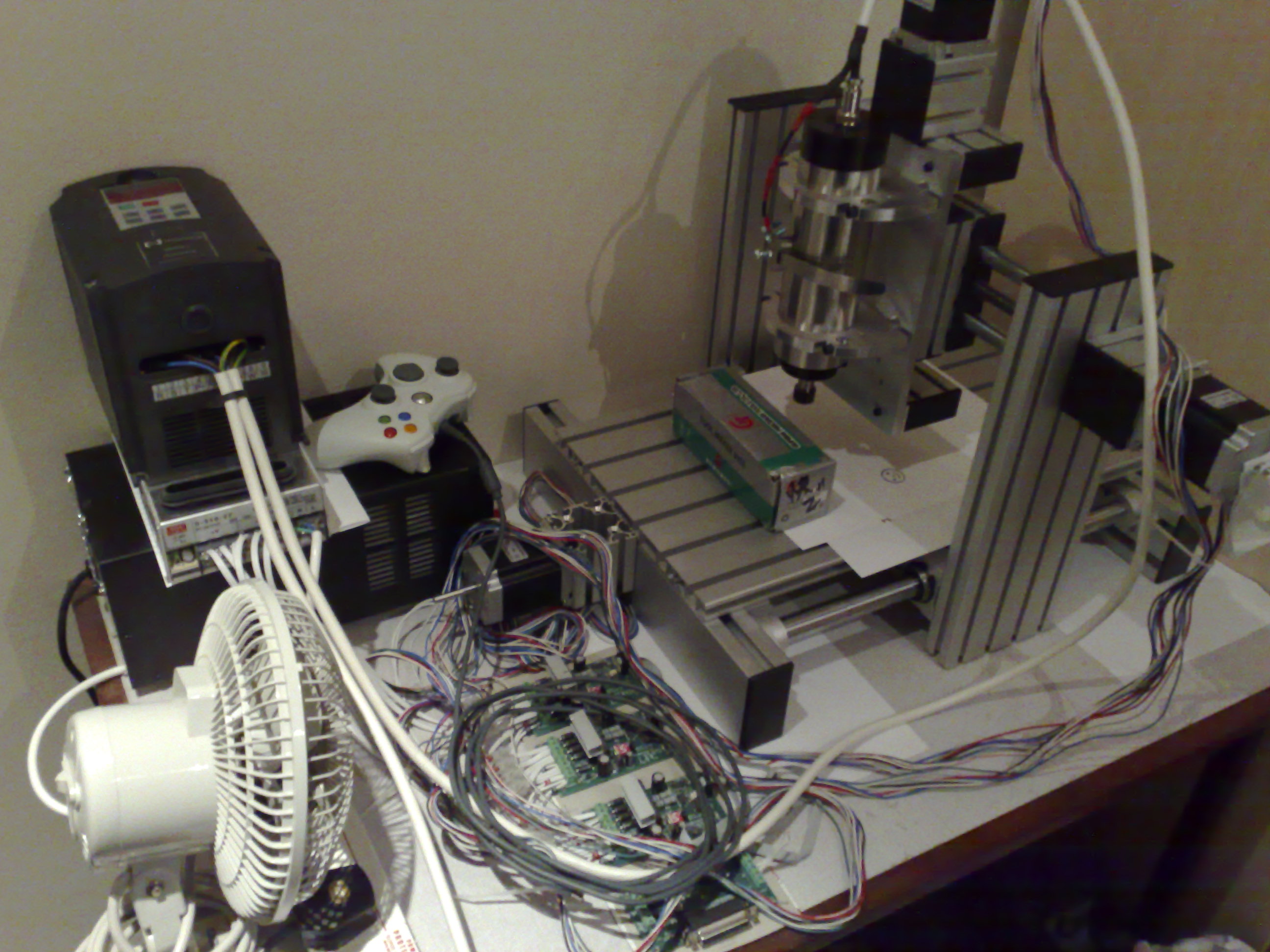
PS: Here’s my CNC machine - You can see the individual stepper motor drivers in front of the fan:
Well I wouldn’t rule out board design at the moment. There are some hefty prices out there, but you can only do one thing at a time. I’m presuming the gecko’s and similar are pretty complex.
Interesting you say about oversized motors, I did wonder. Not sure how far you’d get with printer motors, but they are cheap to play with. I was thinking you’d still want a leadscrew on the z axis.
I’ll probably end up buying stuff off the shelf, but for the fez system it could offer something in the future if it keeps the costs down. I’ve still got plenty to research.
The l298 bridge controls dc motors so it is even more interesting. I’m not sure what software will integrate with that.
I’m pretty curious on this topic also. I’m not sure if I should start a new thread or ask questions in yours.
Chase me with the pick fork and I’ll start my own.
I’m looking to use a Fez or like product to replace the PC/Mach3 and drive a Gecko Driver, but I’m not sure about some aspects. I will be reading from a g-code file to product some fairly simple x/y movements. I do not need to calculate tool paths based on machine wear or anything else fancy . ((I have a cnc mill with pc/mach3, but I need a stand cnc device for some simple tasks))
I may be completely wrong in my understanding, but there are no stupid questions right?
For example, PWM I understand this to be a stream of pulses that I can turn on and off. Now my question… If i want to use that to drive a gecko, do I turn it on and off for each step? Or do I turn it on and start a timer that equals my number of pulses in the stream to meet required steps.
If it’s the first, I think the controller will be easier to build. I.e. I make a loop that increments and sends a pulse for each step until I reach the desired destination. This becomes more complicated with multiple axis concurrent moves. i.e. Without threading, how can I move them at the exact time? They could be relatively close, depending on the speed of the loop, but I’m assuming that I lose cycles turning on and off pwm.
If I turn the pulse on and start a timer, how can I have accurate timers between multiple axis.
I genuinely haven’t arrived at the software controls quite yet. I went through the arduino, ramps 1.4, generation7, rc2c, sanguinolou and the pololu and stepstick (last two are drivers) schematics last night.
It all looks pretty promising as a developmental job for those who wouldn’t know how to start from a chip and get a board and driver out of it.
My next step should be driver control. The drivers themselves can be fairly interchangeable as well, I.e. once you have a driver control software, you plug it in and go, so feasibly it’s just driver board deign that makes them different, maybe plus the odd additional feature.
Feel free to post. It’s only a question of whether you can get the right man or woman’s attention for your question IMO. But I guess sometimes people are less formal.
It’s daft in a way to leave the stepper control untouched. Many people also have the geckos so a fez control and firmware makes them a cheap transplantable add on fom their Cnc to 3d with just a fez and the right firmware would be very appealing.
There’s no need for PWN, just send a pulse (A simple on / off) whenever you want it to move one step. You’ll need to calculate the number of steps per unit distance (Easy) and keep the axes in sync (Hard).
I’m tempted to write a controller at some point.
I unfortunately don’t have Geckos, I have some cheap Ebay version with no mid-band stabilisation which is a never-ending source of problems.
That certainly confirms what I was thinking about just step and direction and ignore everything else which is said in the easy driver code.
Are there any good guides for basically porting drivers. In some regard I don’t think you’d have to know how to scratch write code at all, but convert pin parameters from one board to another, with it not always being that simple.
It depends on what you’ve porting to / from - In some case the language would be different, in other cases there may be libraries available on one platform which aren’t available on others - In some cases it may just be the pin numbers which need changing.
It’s been a few years, but last time I emailed Maris at Gecko the step was 2us wide pulse.
Correct my if I’m wrong, but if you have a 1.8 degree stepper, that should be 200 steps per revolution.
For easy math, if your using .5 lead ball screw. You are turning 2 turns per inch of 400 steps. If you have 2 axis going at the same time, your putting out 800 steps per inch. Now say you want to have a slow feed of 20 inches per minute. Your looking at 16000 pulses per 60 seconds or 266 pulse/second.
(What if your using servos with quadratic encoders that increase the steps tremendously?)
Is it feasible for the micro controller to loop through code and turn the pulses on and off at 266 times per second with the overhead of handling any logic/math? i.e. You ran the machine into an limit switch, or you want to decelerate when your within 1000 steps of your destination?
I guess my concern is that the micro controller won’t have enough horse power to be able to act as a pulse generator for multiple axis and keep them synced while moving at a decent speed. That’s why I thought the PWM would be a better option, since you don’t have the overhead of generating the pulses.
However, I’ll be the first to admit my experience with micros is very limited. I just know this will be more complicated than blinking an led on and off per each step.
How would you calculate the time required to turn a pin on and off? I’m assuming that there is a known time value.
I believe that it’s been said in other threads that one can achieve several KHz when simply toggling a pin on a 72 MHz FEZ such as the Panda or Cobra.
So if you only need 266 per second (0.3 KHz) then you should have plenty of free time to do whatever. Much more if you’re using one of the faster FEZzes f.e. a Hydra, or one of the new Cerberus boards.
Of course, if you’re using RLP, then you can achieve much faster times. Probably MHz or more on a single pin.