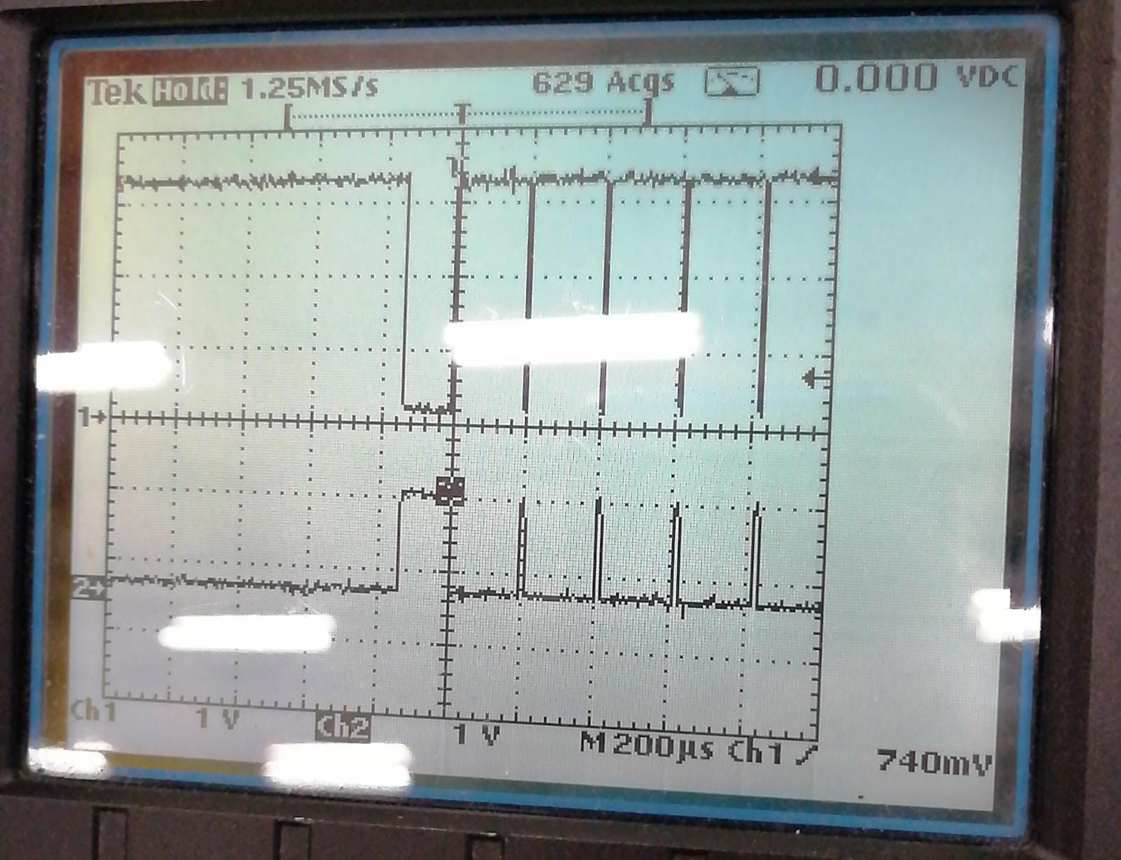
It is 100 kHz. Sorry, I should have mentioned that the regarding scope picture is the direct output of pin 10 of the SC20260N controller (they have removed the 100 ohm resistor to be able to measure between the controller and the CAN receiver).
We use 11 bit and it should resemble the characters “Hello.” as seen in the screen print of the USB can interface output. I will post some scope pictures.
We are puzzled because I retrieved the app from my development board (SCM20260D rev. C) which I get perfect results even if I change baudrates with the help of the timing calculator and downloaded this app in to the prototype board (SoM SC20260N).
Can anyone explain what the exception error we get (picture of tinyCLR config uploaded in previous post above) means?
What have you got connected to the BUS for testing? Is the scope showing us the RX pin of the transceiver or the TX from the CAN controller?
I assume you mean 100Mhz bandwidth?
What are your timings? Are they 100% the same as the other device on the bus? Can you capture the ACK part of the packet with the scope and be sure that the other device is acknowledging the packet?
Something like the Saleae logic analyzer is a really handy tool to have as part of your test bench setup as it can decode CAN bus data as well as SPI, I2C etc.
Do you keep S pin LOW all the time? It should only be HIGH if you want to stop any transmission on the bus. For normal operation, it should be LOW all the time. It should not be toggled if you want the CAN controller to ack all bus messages.
It is like in the small piece of code I posted earlier, I drive both CAN_S and MAX_R_W outputs (from the posted schematic) of the controller low in the first lines of the Main() function.
var gpioController = GpioController.GetDefault();
    //Disable modbus tranceiver
    var modbusTranceiver = gpioController.OpenPin(GHIElectronics.TinyCLR.Pins.SC20260.GpioPin.PH4);
    modbusTranceiver.SetDriveMode(GpioPinDriveMode.Output);
    modbusTranceiver.Write(GpioPinValue.Low);

    //Enable CAN bus tranceiver
    //A HIGH level on pin S selects Silent mode. In Silent mode the transmitter is disabled,
    //releasing the bus pins to recessive state.All other IC functions, including the receiver,
    //continue to operate as in Normal mode. Silent mode can be used to prevent a faulty CAN
    //controller from disrupting all network communications.

    var canTranceiverSilentMode = gpioController.OpenPin(GHIElectronics.TinyCLR.Pins.SC20260.GpioPin.PK1);
    canTranceiverSilentMode.SetDriveMode(GpioPinDriveMode.Output);
    canTranceiverSilentMode.Write(GpioPinValue.Low);
We noticed if we do not actively drive the pin CAN_S low, there is no CAN activity.
But it still doesn’t explain why the controller stops with an exception. The controller should always continue doing its job, even if the master stops receiving messages. This is quite unacceptable for our application, they are all stand alone pressure regulators which should control the pressure independently… Until now no one from GHI Electronics has explained what the message means, which I have asked several times and the message is coming from the GHI firmware right?
What I would do? Hey a CAN transceiver breakout boards for $2 and wire it to dev board to verify it is working. Then write to the board and compare. On the board, wire it directly to the SoM.
Take steps to narrow down the problem. Probing and guessing it’s cut productive.
Another option, send us your board with a check and we will do the work for you. We could use some beer money
Thanks Gus, I will discuss the options with the client, we don’t get much further this way, you are right.
The difficulty I have is, that software and electrical engineering is not happening under the same roof… this leads a little bit to finger pointing
They do under our roof and we are ready to help. I am sure it is something silly you have overlooked but that silly thing can be a week of frustration!
Probably a good idea to consider the hardware as the issue base on the fact that you said that it works 100% on the dev board. I don’t see the transceiver as an issue either but you never know.
We will try to use two SN65HVD230D transceivers in between two controllers.
I was able to reproduce the exception error on the development board also. When I stop the USB CAN interface connected to the development board, I get the same exception error:
Uncaught exception
Done.
Waiting for debug commands…
It is clear that there has to be something listening on the other side. Although this makes sense, how can we prevent the controller from stopping? Is there a way to pause sending the CAN messages, or is there a way to ignore this so the rest of the program will still be executed? I have tried a few things with using try/catch, but it keeps stopping. The debugger says “Waiting for debug commands” is this coming from the TinyCLR config application or from the SC20260? Is there any way to use different settings in VS2019?
I see it now. Your CAN controller is likely going off bus and this is normal. This happens after a number of messages are attempted to be transmitted. The CAN controller is expecting an ACK from each device on the bus. Without any devices, it will timeout and probably going BUS OFF.
Check for BUS off after you get the exception and then reset the CAN controller. It should return to sending again but will create the error again. See if that works.
Thanks Dave, this narrows it down a little bit more. And I totally agree this is normal behaviour of the CAN protocol. I have one master device (PLC) which interfaces with 30 slaves (SC20260), it will be very exceptional that there will be no device left to acknowledge the messages. However, your suggestion does force me to think about improving the application. I will send an incrementing byte value from the master, if a slave does not see change in this watchdog value, it means that the master interface PLC died, so no use sending any more messages over the CAN.
However, it still does not explain why the board with NXP chip does not send a valid CAN signal which receiver side can interpret. This is why we try to cross connect two boards with SN65HVD230D to rule out the controller implementation on the board. Maybe it is power related or timing issues, who knows.
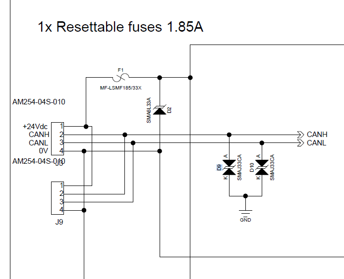
I really wanted to give you the beer money Gus, but I think they have found the problem. Apparently there was a component mix up in design/BOM assembly, they placed uni-directional (SMAJ33A) diodes on the CAN high/low lines, which short circuited the CAN lines. Therefore the signal was very weak, hence I did not measure the expected voltage on the CAN lines:
In the meantime I continued testing on my development board, and I think I came across the same problem which was mentioned by Luca earlier in another post (CAN limitations?).
I also get a “ReadBuffer full” error after 30 seconds. The CAN bus is configured at 500K but the speed of the messages are not spectacular at all. Cyclically 4 messages every second.
I suppose I need to upgrade to a preview version to fix this right?