Seth here. So, I think I am stirring up trouble but I do not want to do it. Anyway, here is how it goes.
I ordered another ServoCape
Made it work
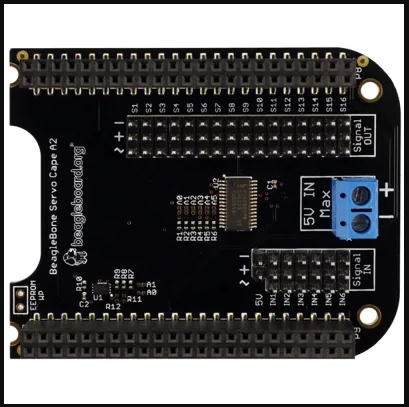
Realized the Signal In headers are missing
a. Just like w/ my previous ServoCape
Does the ServoCape come w/ Signal In headers like photographed in the distributor websites?
Seth
P.S. Either way, I contacted mouser.com again. If this Cape is in the works for a reboot, good! It is very nifty and works well, i.e. esp. when using many servos in rotation. So, if anyone has any thing, at all, to say, please come forward. I feel like a middleman and I think I harassed the wrong people about this concern. Maybe?
you realise that headers are simple to install yourself if you have the tools, right? Having said that, there’s no detail in the Mouser product listing or github that says whether they should or should not have headers installed, so you’re within your rights to ask the question (just remember this is a beaglebone.org product, and GHI had a part in it but aren’t responsible, so there’s likely a better place to ask than here).
Anyway, Signal In, what are your questions? Is it just that you think you have nothing to plug in your device(s) to? What devices might they be??
OK as I said, GHI were tangentially involved, but are neither the reseller or the distributor of these products. And headers are 100% consumer items, many devices you will buy these days comes with unpopulated headers and expect you to solder them on, depending on what you require you may choose male or female headers or… who knows!
You will need to be specific in what “signal in” devices do you want to use. Remembering that this is a very specific cape, these connectioned are (I expect) wanting to read a PWM signal in. A sonar device for example may well NOT use PWM signalling of it’s detected range. You may well need a I2C or SPI or serial input, but that will completely depend on what module(s) you are looking at.
I didn’t check the schematic before, but now I have. The answers are there. You can check it out too and come to your own conclusions.
The layout of the pins for the input is in “standard” servo type connections, but the data pins are routed back to the main Beagleboard on various pins, and you’d need to look at those pins and see if you can use them for your module(s), once you figure out what you want. The + and - are simply connected to the + and gnd rails, use them if you want, or don’t…