Hi gang, I need a bit of advice from you 4-20ma instrumentation experts. I have 4 - 4-20ma sensors that I want to input into a sitcore product (probably the portal), so I can display well and tank water depths, along with 10 or so digital values (tank float switches and misc alarms). The portal will be in the house, the sensors and float switches are in a separate building about 125 feet away. I have 2 unshielded 4 pair (no ground wire) ethernet cables connecting the house with the remote location, so I’ve got 16 (8 pair) conductors to work with. I could route the 4 4-20ma sensors to the house using one cable, which leaves me with 7 available conductors after allowing for a ground, not enough to cover off all of the digital signals.
I could install an analog to digital chip in the remote location and use I2C or SPI to read those values, but I don’t think I2C or SPI over 125 feet of wire works so well. Instead I am thinking of just using resisters in the 4 4-20 sensors at the remote location, and just measure the voltage (would require 4 wires (plus ground) instead of 8 wires). I don’t expect much signal interference on the cable as everything is 10ma or so low voltage signaling. Should this work?
Running the voltage signals that far will increase your chances of interference as well as the voltage drop of the wire. Why not put a SitCore device in the remote location with the I/O and it can communicate with the portal device over Ethernet.
As an alternative, and probably the quickest way to get it done, is to use some MODBUS I/O to interface to the sensors and the portal device would poll the I/O for the data.
I would recommend two items from AutomationDirect:
Open Source Controller. It is an Arduino-based modular PLC. There is an ethernet expansion card available. You could roll your own protocol between the PLC and your Portal with TCP or HTTP. You could also use MODBUS libraries as well. The only limit is what you can program on the Arduino. (I have visions of a SitCore based processor for it. I just have not had the time.)
(https://www.automationdirect.com/adc/shopping/catalog/programmable_controllers/open_source_controllers_(arduino-compatible)#)
Depending on your 4-20mA devices and reading analog input types, you should be able to get away with five cores for your four devices.
The way we run ours with sinking inputs, you would run your common 24V supply out to the field devices +ve side, then run each of their -ve loop lines back on a separate core into your analog input device, where they feed back through the internal sense resistor to 0V/Ground.
If your inputs are sourcing, go the other way, and back on a common 0V/gnd core.
That way you should be able to get your 4 x 4-20mA and your 10 digital signals back over the 16 cores, possibly with one spare.
4-20mA will be fine over that 125 feet of cable if there are no AC signals in the cable bundle. If the only thing in the cable bundle is 4-20mA, DC power and your digital signals, it should work fine.
For your digital, you could run and RS485 on one pair with a small micro at the remote end to interface the digital signals.
I’ve ran 4-20mA pressure and temperature sensors over 1000 meters of single core steel tube cable used for downhole sensors and it worked well. The only issue was when the variable speed drive was operating I would get some noise but proper grounding and isolation of the 4-20mA ADC sorted much of that out.
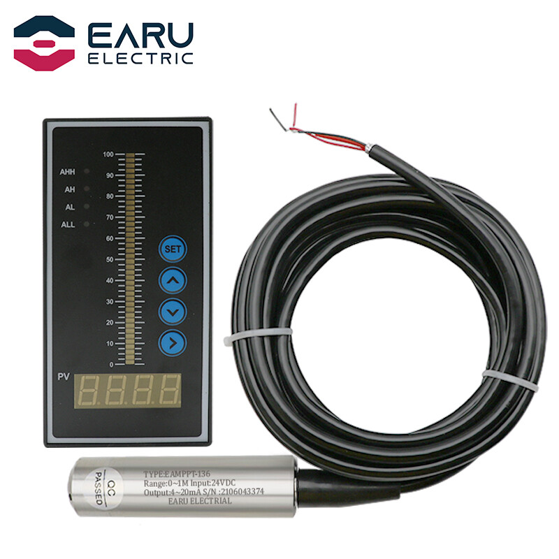
Thanks guys that’s great, i thought I’d be ok running only low amperage DC signals together. Using this cheap stuff from China for the well monitoring, I order the transducer with 100 feet of cable so no underwater splice. The controller is like $20US and cycles the well pump between low and high set points, which works great for low volume wells where you want the pump to automatically shut off when the level gets too low in the well. Using a 24V DC low flow rate pump that works really well.
@c_born, I’ve got 2 separate types of sensors, 2 running out of the Chinese controller, and 2 that I supply power to. I am assuming that I should be able to set them up to be all sinking or sourcing, since I can control the operation of the tanks sensors…
The Chinese controller supplies 24VDC to the sensor, the return (black wire) comes back through the controller current sense to ground/0V. You’ll have to make sure you are running off a commoned 0V at the reading end, and sending out a single 24V line, if you are going to common the 24V at the field end. Are you supplying the controllers with 24VDC, or AC and using their 24V? If the former you are fine, if the latter probably best to just use the 24V from one of them, to avoid contention.
Internally, we have other PLC based products that do exactly this. To get around it, we buy 8 channel ADC modules that then communicate over MODBUS485 (which has a maximum rated cable length of 1200m) back to the PLC. This same design we have also implemented on a TinyCLR based instrument to handle 24V digital IO for integration into a PLC cabinet with no issues.
You would theoretically need 24V out, 485 +, 485 - and 0V in a cable and that would be all.
I have a 24dc power supply already set up at the remote location, so it would probably be easiest to use that to power everything including the Chinese controllers, I didn’t know you could power them directly that way - I had ordered them with 120vac inputs but shouldn’t have bothered, they sell them with 230vac as a default, as you probably know. Question: how do you connect 12vdc to these units - just connect them to the 12vdc terminals and back feed the circuit boards? If so that should work fine, then I will have one common ground for everything, and i can power the micro with 3.3v by stepping down the 24vdc and won’t need a separate power supply at the house…. think I can go higher on that voltage but will check the specs on the portal….
using 485 would work fine as well by the sound of it, but as I have the conductors already in the ground may as well use them… also saved me from having to have a remote device to manage I presume…
this is true, but in our experience, these units are pretty fire and forget. That being said, 4-20 mA is pretty robust when it comes to outside EMI so you would probably do just fine running the conductors straight. I would still suggest using a plug and play 4-20 mA analog input module though instead of trying to jury rig a current input directly into SITcore module - no use reinventing the wheel when these can be had relatively cheaply. They’re everywhere and really easy to set up.
“Analog Current Signals (0-20mA, 4-20 mA): Typical industrial position sensors with an analog current interface can tolerate significantly longer cable lengths compared to comparable voltage interfaces. Again making a somewhat broad generalization, analog current signals can tolerate cable lengths up to 500 feet.” - source
I don’t have first hand experience with these units, just going by what they say on the website: https://www.aliexpress.com/item/4000101497558.html
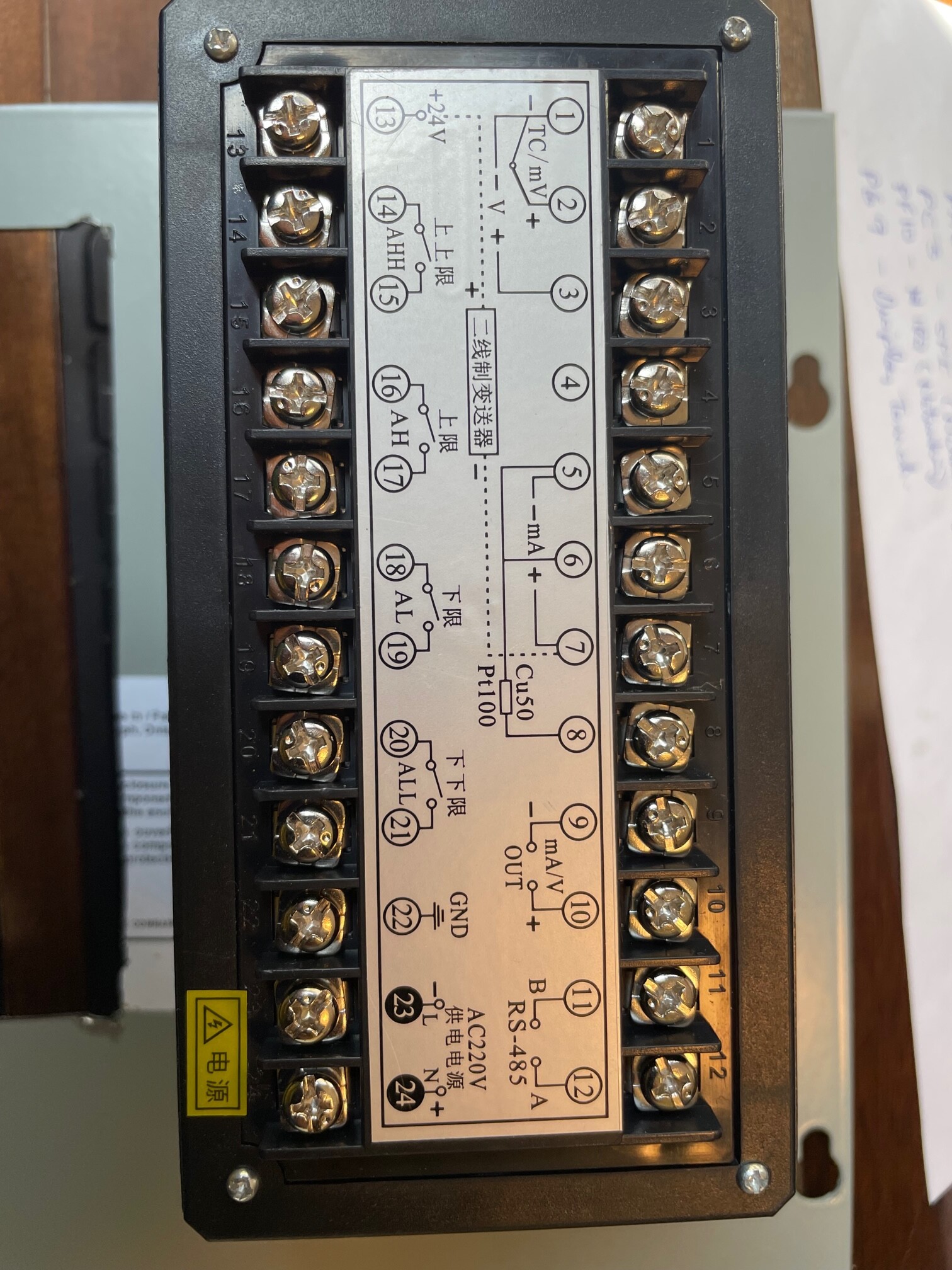
Says you can supply with 24VDC, and the picture of the terminals show a + and - on the AC220V L and N terminals, so I would expect you would connect your 24VDC there. I have a bunch of 4-20mA signal conditioners here (another make) that work that way.
I have checked on the 4-20ma output, and it looks like I will be able to send out a common +24vDC supply for all sensors and read the return signals through a resister, using a common ground for all. And I think I can use the 24V power supply I have to power the 2 controllers by connecting to the +/- 24DC on terminals 1 and 13 and ignoring 23/24.
Possibly, but that’s not how I read it. (13) is your +24V out from the controller to your 4-20mA field sensor, with the return on (7). Internally the current would then flow through the sense resistor to (5), which is (probably) internally connector to 0v. Pin 1 is the -ve connector for thermocouple, volts (3, via divider) and mV (2). For a quality system those inputs would be differential and isolated from the power supply, for a cheap system it is probably single-ended with (1) connected to 0V. In the latter case you will probably be able to meter it and find (1), (5) and (22) are internally connected.
(23) and (24) are labelled as “power supply” (Chinese), and with both AC220V and + and - symbols. My PR-4116 units work this way, accepting 21.6…253 VAC, 50…60Hz or 19.2…300VDC on their power supply terminals.
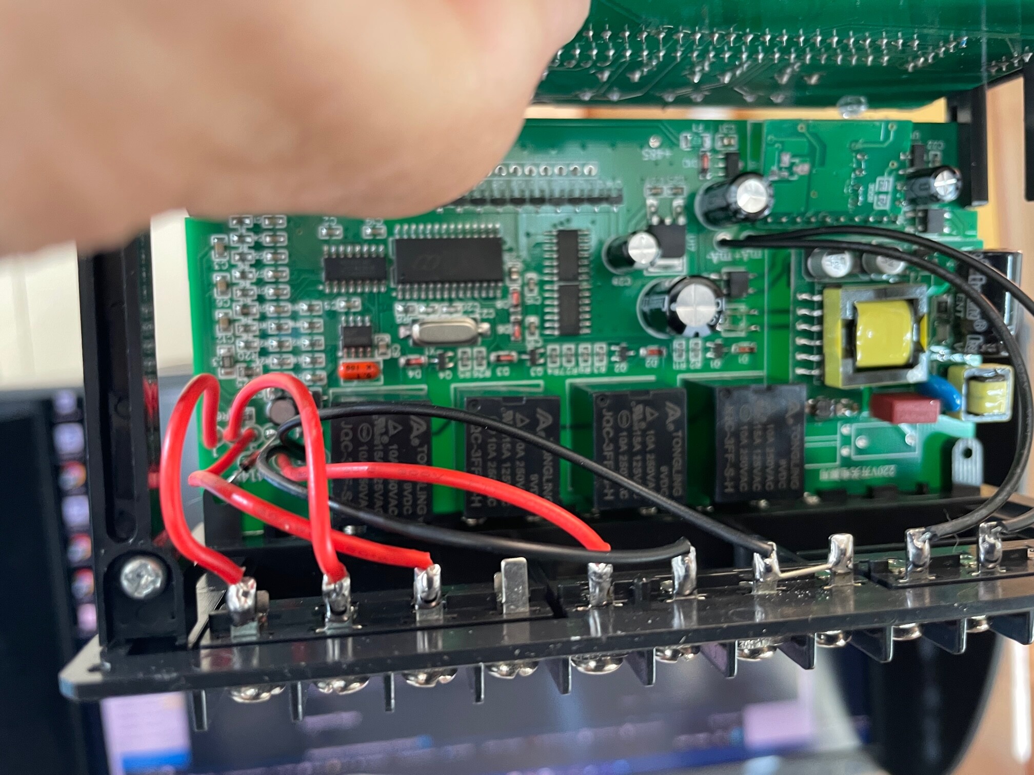
Of course like any engineer the first thing you will want to do is pull the things apart and check how they work!
Yuppers 1 and 5 are connected, but they are not connected to 22 gnd, so it seems to be isolated. I have the sensor connected as you note, and can read a voltage between 5 and 7 (currently about 1 volt, well is at its low point), but not between 22 gnd and 7. That being the case I can’t use a common ground approach I’m guessing… Unless I can supply an independent 24V source, and connect the sensors to that source, to 7 and 5, and use 5 as the common ground?. That means I would be connecting terminal 5 between two of these controllers together with the power supply ground. I do of course get a voltage between 13 and 7, and I could use a common +24 wire that I could take back to the micro as a reference and adjust readings appropriately.
And I’m not an electrical engineer, but only a civil, but hey that doesn’t stop me from prying things apart! terminals 1-7 have individual wire connections to the pc board but 1 and 5 connect on the PC . It also looks like 22 gnd isn’t connected to anything lol.
Sounds like 22 is just a frame-ground point then, and 1 and 5 will be the 0V return for the 24V.
Were you planning on reading all four 4-20mA signals with the Sitcore, with two of them also going back to the controllers? Easiest way would then be to pick up those two as the voltage across 7 and 5, use 5 (=1) as your ground reference, and add the other two channels back through your own sense resistors (say 100 ohm) to that (5)(1)(0VDC) common reference point.