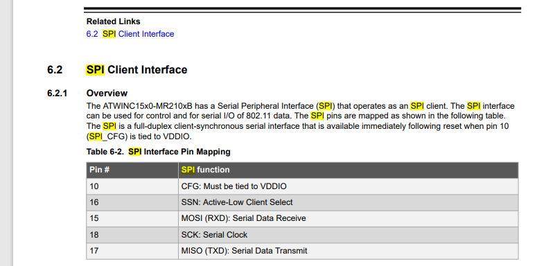
if you build your custom module then the pin#10 CGF need to be set for SPI mode.
Double checked that - it is tied to VDD but is still not working. Reset and enable are tied low too, as is recommended in datasheet. I follow the cod e in the tutorial nearly line by line. I currently have the code stripped down to literally just the network - nothing is enabled, no other pins and it just is throwing an Invalid Operation Exception. I’ve tried switched SPI buses, moving pins around, with and without expanded flash, tested the breakout and the bare module, tried our custom boards and the SCM20260-Dev, nothing seems to work. Is there any way to get more verbosity on why it’s failing? do you guys have like a master list of pins that the firmware uses?
Edit - I suck at soldering, disregard this.
During the COVID period 19.5.2 was the only WINC that was on the market and I have updated at least fifteen to the latest fw version… so see here
https://forums.ghielectronics.com/t/atwinc1500-mr210pb1952-firmware-update-via-uart/24323
Some versions of pre-assembled modules mount a pull-up resistor on the reset line and If you connect an MPU, the reset line is high on power up before it intervenes.
The initialization sequence of the serial requires that the reset is at a low level upon power-up so remove it to update the firmware and if you want to put it back in its place at the end of the update.
I did see that - this is on 19.5.4 though so it should work. If i continue to run into issues, I can definitely try updating.
I too had struggled for some time with the SPI problem. So I tried to connect via serial. At that point I noticed that some times the module was responding but lost the serial connection. Then I found the manual update article where they explicitly said batches had UART test routine not working… at this point I think updating is the only option.

Here the WINC part in my definitive board
tied to low or pulldown? I don’t think the module work if these pins low during communication.
Pulled down, sorry. the data sheet calls out using a 1MΩ resistor to pull them down on powerup.
Sorry but something occurred to me …
I still have to investigate … what MAC address do you give to WINC1500?
Are you using the default or set it yourself?
I ask you this question because I had found that with some MAC addresses when I executed the enable of the module I got the exception.
Now I have a randomizer that sets the MAC with at least the first three digits with the Microchip ones and I have not had this problem anymore. I never managed to figure out if it was a problem with the module or the access point but I had solved it like that.
Did you look at scope for signals?
So I was able to solve this - I was using the Adafruit breakout board which runs everything (SPI signals included) through a level shifter - I believe it added a time delay to my SPI clocks sufficient enough to throw everything off. At 115K baud, the UART was working fine when configured, but my SPI bus is cranking at 32 MHZ so i wasn’t getting a response.
On the sample directly on my custom board, I had my reset pin pulled high instead of low. I desoldered the pullup resistor and jjumpered reset to GND_1 with a 100K resistor and rechecked my soldering job and it works perfectly now. I think. It enables and the bus is working, but I have been striking out finding a u.fl antenna that works, so the WIFI can’t find any networks, and when set to access point it does not appear on my phone.
Point being, we’re past the GHI firmware portion.
I use the default MAC address that comes on the chip, but we purchased an OUI from IEEE so I would generate our own EUI48s if the default didn’t work.
Earlier I said reset and enable pins should not be low :d.
Also, I don’t think 32MHz work well if connection is not clean.
try to set 4MHz to make sure everything works perfectly first then go higher.
Most of delay time is on processing packages internally between SITCore and module, not SPI speed. So not much different from 4,8 or 32MHz.