Would anyone have any code they can share? I am having trouble figuring out where to get started reading the MAX31855. I am new to gadgeteer and would appreciate any help . 
We are working on a thermocouple module with same chip. We will share the code soon when ready.
1 Like
Gus - I look forward to it.
I’ve got some code, will share it soon, just tied up at the moment in work, but will post soon
Great news, I’m thinking of building my own reflow oven in near future, so that might be very usefull!
@ WouterH - I’m also thinking of a DIY reflow oven. From my initial research, it looks pretty straightforward. Track me down when you’re ready to start.
Iam also waiting for a driver/code for this chip. Anyone out there, any luck?
Is there any luck on a driver/code class for the MAX31885 yet.
I have been trying a few things with no luck.
I am also looking for some help on a SparkFun geiger counter interface to Spider via USB Host.
My system is a controller for a project I have been working on for a while.
so any help would be appreciated.
Looks like ti is working so we will have a module with driver this month.
If you can’t wait, the datasheet is very clear on how the chip works.
1 Like
So how is the module configured?
Ineed a reading >500C maybe to 1600C.
Can I place my own K type on the module?
THanks
Yes you can use any K type thermocouple
I’ll take 4.
I would have and do understand the datasheet, it has just been a long time since I did hardware stuff.
Thanks for the help.
Now any ideas on a geiger counter. I need a control system on my reactor.
thanks.
Dan
Any word on the module/driver yet. Just checking.
Thanks
It will be announced and will be on catalog page when ti is ready. Design to production take 4 to 8 weeks minimum.
Thanks.
I know this is an old post …
I bought the thermocouple module and trying to understand the correct way to connect it to the board as there are 2 connectors from the thermocouple. Am I suppose to connect both connectors to the board?
Regarding the programming part, what are the definitions of internal/external temperature? This is my first exposure using thermocouple. Been waiting for more than a week for answers to these questions from GHI, with multiple requests.
Maybe someone from the forum have the answers …
Thanks.
the forum is definitely the right place to ask for support, any other channel will not get Gus’s direct input ![]()
Thermocouple module https://www.ghielectronics.com/catalog/product/397 ? By two connectors do you simply mean the double-ended spade lugs that the image on that page shows as being on the non-sensing end of the thermocouple? Those lugs are not designed for a simple screw-down connector so you can safely use them with one arm of the U shaped lug in the screwdown connector, and I suggest you leave the other end protruding from the connector on the outside of the board so there’s no chance the two will touch at all.
As for internal and external temperature, the definition of those is based around the actual chip used on the module for sensing. Thermocouples are sensitive devices and the amplifier chip adjusts the temperature read from the thermocouple based on what the temperature is at the"cold junction", i.e. the temperature of the chip, in what is called cold junction compensation. It would appear to me that the internal temperature is a measure of the CJ temp, and the external temp will be the compensated measured temperature. If you want to dig deeper here, the TC chip in use, MAX31855, is documented Mixed-signal and digital signal processing ICs | Analog Devices
Hi Brett, thanks for the response. Yes, I meant the 2 spade like ends. One has a red lug and the other is blue. So, based on your description, I am supposed to connect one arm of the U shaped (red) to the “+” terminal on the board and one arm of the blue lug to the “-” terminal of the board? Or I got the “+”, “-” reversed? If only one arm of the lug being used, why use the “U” shaped type end?
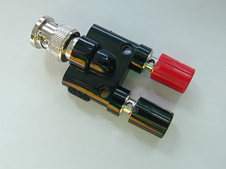
Why the U shaped end? Because that’s a standard connection type for thermocouples, to be screwed down under a binding post - see Binding post - Wikipedia and the red and black portions of http://upload.wikimedia.org/wikipedia/commons/thumb/0/0e/Binding_post_adapter.JPG/320px-Binding_post_adapter.JPG
Red is positive.