Hi, I’m having troubles with this driver. When I energize the circuit, the driver is shorting to supply. So, I remove the driver, and his pins (VBB and GND) are not short-circuiteds. I have no idea why when the driver is soldering in the board, is closing short. If someone have had this problem, please, give me a light.
This thread is from 2013… only 7 years ago  What are you trying to do?
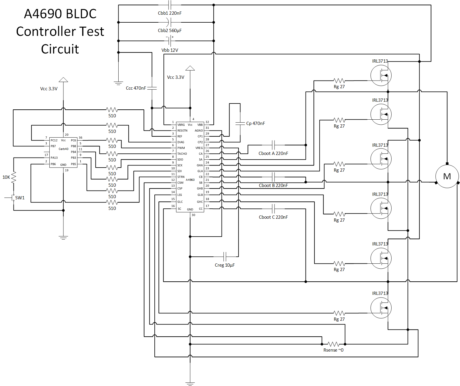
Hi, I’m trying to validate the workig of this driver for in the future using it in a BLDC controller. I know that the publication is old, but it’s worth trying. This is the only place in the web that a found a discussion about this driver.
Hello all,
I am the one who has created this driver, and I am still around. It was only 7 years ago 
What files do you need - I’ll repost.
1 Like
Welcome back 
Hi m0rda, Do you have the code ? preferably in .txt
Hi, I’m having troubles with this driver. When I energize the circuit, the driver is shorting beetwen VBAT and GND. So, I remove the driver, and his pins (VBB and GND) are not short-circuiteds. I have no idea why when the driver is soldering in the board, it’s closing short. I’d like your opnion about what could do. I’m conecting VBB and VBRG(High-side drain voltage sense) togethers, because I’m using the baterry voltage to supply the VBB pin. Do you think that I need to use different wirings to conect VBB and VBRG even they are conecteds at the same point (VBAT) ?
Hello,
This circuit has some electrical magic. I have rerouted 3 prototypes before it was working properly. The same schematics, but with different routing would give different results. Although Vbb and Vbrg are connected in a circuit, where this connection happens, matters.
The general rule is to make tracks as short as possible, especially in areas, adjacent to transistors, as well as Rsense and Cbb2.
For Rsense I was using a shunt made of thick copper wire - see the image of one of prototypes.

Also, I need to say, that it is important which transistors you are using to drive the motor. My prototype was running a brushless motor at ~12V and up to 70A of current, however, I doubt that the current was anytime over 50A.
2 Likes
Thanks Gus,
I wonder where now is the proper place to re-upload the source code?
NuGet? Or GitHub?
Back in 2013, I remember, there was a very convenient “codeshare” section in this forum, where people were uploading their .NET MF drivers for various devices. Is it scrapped completely or moved somewhere?
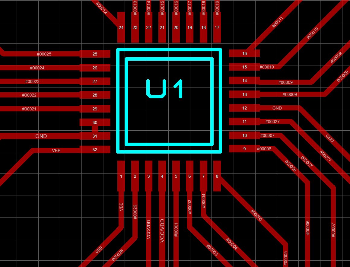
Hi, seen the photo of your board I realized that you dint’t conect the pin 30 - GND. Am I correct ? If yes, why ? Did you have problems when you grounded this pin ? I realizad too that you used different traces for VBB and VBRG. Maybe, the cause of the shorts beetwen VBAT and GND in my board is because I have conected the two pins instead using differents traces.
Thank you beforehand.
Hi,
In my layout pins 30 and 31 are connected with a very short trace, see the drawing.
I cannot recall there were any problems with grounded pins.
I used two different tracks for VBB and VBRG. While VBB goes from pin 32 to the closest place where the battery positive enters the board, VBRG goes from pin 1 to the point where the battery positive connects to transistors’ drains. For that device such a connection is important, as well as a proper shunt Rsense.
Hope that helps.
1 Like
Hi Ilya Kretov, is this your name?
My name is Thiago. Thank you for answering so fast my questions. I will change the conection of VBRG pin then. For while, my board stopped to shorting beetwen VBAT and GND (because I removed the trace that conected VBRG to the pin VBB). I’ll use a different trace for this conection now.
But now, when I solder the charge pump capacitor that goes beetwen the pins 27 - VREG and GND, the driver is shorting again. The most odd is that when I turn off the circuit, there’s no short beetwen the driver’s pins. Then, I unsolder the capacitor and the short stops, but the capacitor isn’t in short when I remove it form the board kkk I have used two different capacitors (ceramic and aluminium eletrolytic), and both, when I solder them in the board, makes the driver short-circuits.
Do you have some idea of what could be ? I belive that perharps the fact of the driver was shorting before, have caused some damage in it internal regulator, that now is causing this strange problem when I solder the charge pump capacitor. In soon, I’ll change the drivrer for a new one, and test if this problem keeps.