EXEC : error : L6221E: Execution region ER_RAM_RW with Execution range [0x20000188,0x20006220) overlaps with Execution region ER_STACK_BOTTOM with Execution range [0x20004000,0
x20004004). [D:\netfm\netmf44RTW\Solutions\STM32F401\TinyCLR\TinyCLR.proj]
my defination is as below
<ExecRegion Name="ER_VECTORS" Base="%SCode_RAMBaseAddress%" Options="ABSOLUTE NOCOMPRESS" Size="%Code_SRAMSize%">
        <FileMapping Name="*" Options="(VectorTable +FIRST)" />
    </ExecRegion>

    <ExecRegion Name="ER_RAM_RW" Base="+0" Options="ABSOLUTE NOCOMPRESS" Size="">
        <FileMapping Name="*" Options="(+RW-DATA, +ZI)" />
    </ExecRegion>

    <ExecRegion Name="ER_RAM_RO" Base="+0" Options="ABSOLUTE NOCOMPRESS" Size="">
        <!-- Flash programming from Flash is safe on STM32 -->
        <!-- No need to place Flash programming code in RAM -->
        <!-- <FileMapping Name="*" Options="(SectionForFlashOperations)" /> -->
    </ExecRegion>

    <ExecRegion Name="ER_HEAP_BEGIN" Base="%Heap_BaseAddress%" Options="ABSOLUTE UNINIT" Size="">
        <FileMapping Name="*" Options="(SectionForHeapBegin)" />
    </ExecRegion>

    <!-- everything between heapbegin and heapend will be allocated for a heap -->
    <ExecRegion Name="ER_HEAP_END" Base="+%Heap_Size%" Options="ABSOLUTE UNINIT" Size="">
        <FileMapping Name="*" Options="(SectionForHeapEnd)" />
    </ExecRegion>

    <ExecRegion Name="ER_CUSTOM_HEAP_BEGIN" Base="%CustomHeap_Begin%" Options="ABSOLUTE UNINIT" Size="">
        <FileMapping Name="*" Options="(SectionForCustomHeapBegin)" />
    </ExecRegion>

    <!-- everything between heapbegin and heapend will be allocated for the unmanaged SimpleHeap -->
    <ExecRegion Name="ER_CUSTOM_HEAP_END" Base="%CustomHeap_End%" Options="ABSOLUTE UNINIT" Size="">
        <FileMapping Name="*" Options="(SectionForCustomHeapEnd)" />
    </ExecRegion>

    <ExecRegion Name="ER_STACK_BOTTOM" Base="%Stack_Bottom%" Options="ABSOLUTE UNINIT" Size="">
        <FileMapping Name="*" Options="(SectionForStackBottom)" />
    </ExecRegion>

    <ExecRegion Name="ER_STACK_TOP" Base="%Stack_Top%" Options="ABSOLUTE UNINIT" Size="">
        <FileMapping Name="*" Options="(SectionForStackTop +LAST)" />
    </ExecRegion>
@valon_hoti_gmail_com The timing is definitely much different between GHI FW and NETMF 4.4
Under the scope, my i2C appears to be functioning but am getting no response from the devices, hence something must be off with the timing (SPI timing had to be completely re-tuned so I am almost positive the i2C timing is now off from the FW change too), not sure what to do about it though.
There is full continuity on the traces and appropriate 2.2k pull ups. This board and code have been rigorously tested as well. I am contemplating adding shunt resistors to the i2C traces but since they don’t leave the board and weren’t needed with GHI FW, I am skeptical this will solve anything. Also I would rather solve programmatically than have to break the traces on the hundreds of boards we already ordered…
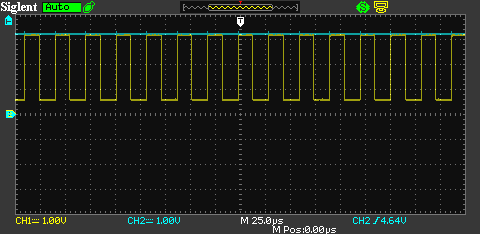
Here is an oscilloscope shot of the I2C config being created upon the start of my code (yellow is SDA, blue is SCL) - notice that SDA is only dropping to 500 mV when going low:
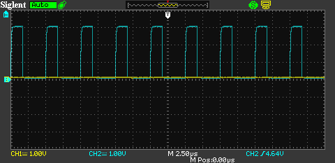
Here is a shot after all i2C transactions have failed / no responses from devices (yellow is SDA, blue is SCL):
…I am not sure what to test or change next.
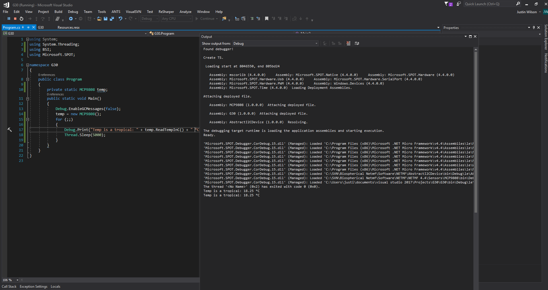
This at least verifies the i2C pins are mapped correctly in the FW and are wiggling from my code.
Tried @Justin’s FW with no luck. I tried enabling the SDA and SCL pins as GPIO and toggled them high and low under the scope. I am seeing some funny behavior with SDA, lots of oscillations when held high, about 200 mV of fluctuation.
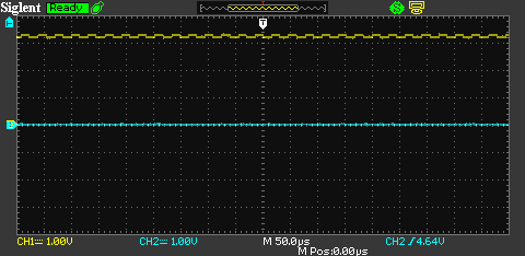
Here is a shot of SDA held high (yellow) while SCL is held low (blue), SCL does not display this behavior when held high it is perfectly flat:
@valon_hoti_gmail_com I have tried 50, 100, 150, and 200 kHz. 1 out of the3 i2c devices has a max clock of 200 kHz. On the GHI G30, 200 kHz was the only speed that would work for all.
I am going to build a fresh board in the morning and see if the problem still persists, I anticipate it will so I am still open to any other FW / software changes.
It turns out it was the board (the only one out of 10 that had the issue)…built a fresh one and the oscillations went away. Everything is working smoothly now!
Haha thank you I wish I could take some days off, worked straight through the weekend on this! Too many other projects got put off for the crisis aversion task force though…back to the rechargeable battery circuit thread I started weeks ago
…definitely having some beers to celebrate though!