So I’ve got movement on a servo (different thead). Now it’s time for a next step in my explorations. I’m trying to determine the pulse width of a PWM signal from an RC receiver.
I am staring at this bit of code which I wrote based on a tutorial. Nothing happens, the event does not fire, while I see a nice block wave on my scope with a frequency of exactly 50Hz and a pulse width of exactly 1ms.
What am I doing wrong?
class Program
{
    private static long _pulseWidth;
    private static long _currentPulse;

    static void Main()
    {
        var gpio = GpioController.GetDefault();

        var signalIn = gpio.OpenPin(FEZ.GpioPin.D2);
        signalIn.SetDriveMode(GpioPinDriveMode.InputPullDown);
        signalIn.ValueChanged += Signal_ValueChanged;
        _pulseWidth = 0;
        while (true)
        {
            Debug.WriteLine($"{DateTime.Now.Second} {_pulseWidth}");
            Thread.Sleep(100);
        }
    }

    private static void Signal_ValueChanged(GpioPin sender, GpioPinValueChangedEventArgs e)
    {
        if (e.Edge == GpioPinEdge.RisingEdge)
        {
            _currentPulse = e.Timestamp.Ticks;
        }
        else
        {
            var thisWidth = e.Timestamp.Ticks - _currentPulse;
            if (thisWidth < _currentPulse - 1000 || thisWidth > _currentPulse + 1000)
            {
                _pulseWidth = thisWidth;
            }
        }
    }

}
Yes I have. I have put a breakpoint on the outer if statement. Nothing happens.
Sometimes the program doesn’t seem to start. It seems to help if I connect the pin after start up. That’s the only moment I have seen the event fire.
Do you know how many ticks there are in a millisecond? I have chosen this window because I have seen a very big number coming by, much bigger than 1000.
Firmware is up to date.
I will try a second board. I bought serveral. If that does not work I may try an Arduino I have laying around. The thought of separating the data acquisition process - I wish to monitor three PWM signals - from the rest is appealing.
Just tested your code, here it works.
Try once more to let the automatic of VS create the eventhandler.
means: signalIn.ValueChanged += then 2 x tab
sometimes VS doesn’t correctly assign the eventhandler.
You took the Pin between D1 and D3 and intermittently connect it to 3.3 Volts (best through a 10 KOhm resistor)?
Good to know that the code works.
Well, good to SEE that the code works. Simulating a signal with 3.3V like you said makes the code work here too! Great idea!
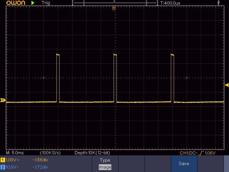
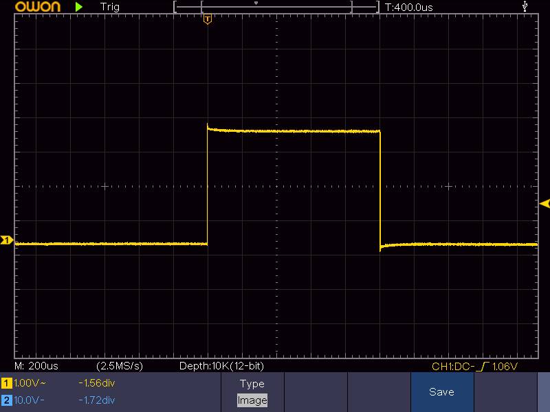
I guess the signal is the cause of my problem, which I can’t imagine:
Period: 20.0ms
Pulse width: 1.010ms
Amplitude: 3.285V
I have added two pics of the same signal:
However I think that handling pulses of RF receivers can be challenging for a device running managed code. Sometimes it may be better to attach a small MCU like an Arduino for the RF Decoding and use something like the FEZ to manage and transmit the received measurements.
Do you know how many ticks there are in a millisecond?
use: var ticksms = System.TimeSpan.TicksPerMillisecond;
I like what you say!
Solutions I find in the big Arduino community look easy. So I have been thinking to try to read the signals with an Arduino Uno I have laying around instead. Then I could connect the Arduino to the Fez with I2C or UART.
I wish to capture three RC receiver signals, do calculations on them and send ten new signals to servos. Separating the intensive work (handling six events every 20ms or so) from the calculations and the controlling of ten servos is appealing. Now you are saying the same thing I may go that way. Although I’m curious whether it would have worked, this marshalling of handling events and doing the synchronous work on one processor.
Why would it be harder to read RC receiver signals with a device running managed code? Because of the managing that is being done in the background?
“Managed code” is synonymous with “management overhead” - so it’s arguably easier to program more complex capabilities, but you lose the real-time, run 100% flat-out that something like an Arduino gives.
The problem is that the events induced by the RF receiver come very often, esp. when the receiver is not sending there come masses of spikes due to noise. Your device must be able to handle all these events in time. So you should ban any Debug.Write commands from the code segment while the device is listening to the input. Debug.Write is time consuming and the interrupts will congest in their internal queue until your program evtl. crashes. So evtl. disable further interrupts while handling the actual one (where it is possible without missing important input signals). Which timespans do you expect for the signals from your RF receiver? How often will your RF-transmitters send new values.
Evtl. you should consider to use RFM69 modules.
-https://old.ghielectronics.com/community/codeshare/entry/1096 @Justin evtl. has some of them to sell, or you can have a look at the Moteinos (Arduino boards with integrated Rfm69).
RC receiver in question is the kind used for model cars or airplanes. First step is to get the electronics working. Second is to build a model. That is yet to be decided.
Three channels:
1 Does not change very often and when it does it doesn’t hurt if it takes a few 10ths of a second before it is processed
2 Does not change at all in 60% of the cases. This depends on channel 1. In the other 40% we need prompt action.
3 Expected to change all the time and needs prompt action.
My plan now is to go for a second board (Arduino) for gathering the signals. Values can be requested by the main board by I2C.
I think I will settle for polling the channels first. When I poll ch. 1 not as frequent as 2 and 3 and 2 only when needed, I think I can update ch. 3 20 times a second or so.
I’m studying on interrupts. But these interrupts may go off at the same time and ‘millis’ and ‘micros’ are not as lineair as desired, so I’ve learned. I think advanced approaches get in to the register of the processor.